Sniff is a "Scratch-like" programming language that's designed to help Scratchers move gently from Scratch to more conventional languages. They can start writing programs, without having to learn a new language because Sniff is based on Scratch. They learn a little more about variables, compiling, syntax errors (!), and they can have fun controlling real hardware while they're doing it.

Tuesday, 12 January 2016

Measuring Cheese with the Esplora

One of the new features of Release 24 is support for the Arduino Esplora. This is essentially an Arduino Leonardo (so compile programs using leo-sniff), with a whole bunch of sensors, buttons, a joystick and a slider built onto the board, so you can start programming without having to hook up extra hardware. As such you could always compile programs to run on it using leo-sniff, but now we've added got hold of one we've added support for all of the sensors.


The foam is acting as a diffuser for the very bright RGB Led

make usb device
make usbConsole device

The main difference between the Esplora and the more common Uno is that they handle their usb communication to your computer completely differently. One the Uno there's a dedicated chip which does nothing but handle the USB, but on the Leonardo and Esplora this is all done in software. This is more flexible, but less reliable. If you have problems programming the board, then pressing the reset button just before you download the program will usually solve the problem.

We need to include the usb device to handle the core of the USB protocol, and then the usbConsole device so that "say" and "ask" get directed over the software USB implementation. These have been stable for some time, but we've recently seen some problems with OSX Mavericks. "ask" in particular seems to have become unreliable. Helpfully we'll get this resolved in the future.

Now for the interesting bits:

#Some of the HW is just atattched to pins:
make redLed analog output D5
make blueLed analog output D9
make greenLed analog output D10
make led digital output D13

when start
.forever
..set redLed to 0.5*((sin of (timer*100))+1)
..set greenLed to 0.5*((sin of (timer*110))+1)
..set blueLed to 0.5*((sin of (timer*120))+1)

The Esplora has a regular LED attached to D13 like most Arduino's but it also has an RGB led attached to pins 5,9 and 10. These support analog output so we have easily mix colours together.

make buzzer digital output D6


The buzzer is attached to pin D6. In fact the "buzzer" is simply a piezo speaker, and to play a sound we need to "push" the speaker in and out at specific speeds:

when start
.forever
...set buzzer to on
...wait 1000 microsecs
...set buzzer to off
...wait 1000 microsecs

There's an accelerometer attached to analog inputs (yes A11 is a real thing - not a typo), and a couple of spare pins D3, and D11 which are brought out on two "tinker kit" headers.

make accX analog input A5
make accY analog input A11
make accZ analog input A6

make tkOutA digital output D3
make tkOutB digital output D11

Though tkOutA and B are labelled as outputs they are direct pin connections and can be used as both inputs or outputs.

You can access all of the above using regular Sniff Arduino code, but the other hardware on the board is a bit more tricky, so we've bundled it up in the "esplora" device:

make esplora device
make temperature number
make joyX number
make joyY number
make joyButton boolean
make esploraSlider number
make esploraLight number
make esploraSound number
make switch1 boolean
make switch2 boolean
make switch3 boolean
make switch4 boolean
make tkInA number
make tkInB number

We've got access to the temperature (though in a previous post I expressed serious doubts about its accuracy) joystick, slider, light and sound levels, four switches and two generic tinker kit inputs (not that these ARE input only).

when start
.forever
..tell esplora to "read"
..say join [switch1] join ":" join [switch2] join ":" join [switch3] join ":" [s
witch4]
..say join "Temp:" [temperature]
..if joyButton
...say "Joy Pressed"
..say join "Joy:" join [joyX] join "," [joyY]
..say join "Slider:" [esploraSlider]
..say join "Light:" [esploraLight]
..say join "Sound:" [esploraSound]
..wait 1 secs


If you have the Esplora TFT screen you can also draw stuff on it, using the standard Sniff drawing methods, having first declared a display:

make spi device
make display esploraTFT device

With the basic stuff out of the way, lets actually do something useful with this...

 it's CHEESE TIME.

In addition to an Arduino Esplora, one of the residents of Snff Manor got a cheese making kit for Xmas. As I'm sure you all know, cheese needs to be matured in a cool place between 10 and 14 degrees. The cellars seemed ideal but some kind of monitoring system was clearly in order.


when start
.set maxTemp to -100
.set minTemp to 100
.
.set displayColor to 0000
.tell display to "clear"
.broadcast updateGraph and wait
.
.forever
..set slowAverage to 0
..repeat slowSampleTime
...set fastAverage to 0
...repeat 10
....tell explora to "read"
....change fastAverage by temperature
....wait 0.1 secs
...set temperature to fastAverage/10
...change slowAverage by temperature
...
...if temperature > maxTemp
....set maxTemp to temperature
...if temperature < minTemp
....set minTemp to temperature
...
...broadcast updateLed and wait
...broadcast updateText and wait
..
..set temperature to slowAverage/slowSampleTime
..add temperature to history
..repeat until not length of history>historyLength
...delete item 1 of history
...
..broadcast updateGraph and wait


There's a lot going on here, but if we start from the middle, you'll see that we repeat 10 times, measuring the temperature and averaging it over 1 second. This makes the built in sensor much more consistent (if not more accurate). Then we compare the measured temperature to the max and minimum, and fire off a couple of scripts to update the RGB led and some text on the display.

We do this 900 times, which is 15 minutes, and calculate an average over this longer period, which we add to a list called "history". This records the last 12 hours of data, and we call a script to plot it on the screen.

make lowestThresholdTemp number 6
make lowThresholdTemp number 10
make highThresholdTemp number 14
make highestThresholdTemp number 20

when updateLed
.if temperature <lowestThresholdTemp
..set blueLed to 1
..set greenLed to 0
..set redLed to 0
..stop script
.
.if temperature <lowThresholdTemp
..set blueLed to ((lowThresholdTemp-temperature)/(lowThresholdTemp-lowestThresholdTemp))
..set greenLed to 1-((lowThresholdTemp-temperature)/(lowThresholdTemp-lowestThresholdTemp))
..set redLed to 0
..stop script
.
.if temperature <highThresholdTemp
..set blueLed to 0
..set greenLed to 1
..set redLed to 0
..stop script
.
.if temperature <highestThresholdTemp
..set blueLed to 0
..set greenLed to ((highestThresholdTemp-temperature)/(highestThresholdTemp-highThresholdTemp))
..set redLed to 1-((highestThresholdTemp-temperature)/(highestThresholdTemp-highThresholdTemp))
..stop script
.
.set blueLed to 0
.set greenLed to 0
.set redLed to 1

I've set up four constants using the new Sniff R24 syntax. lowestThresholdTemp is 6, and using the word is exactly the same as using the number. This means we can push these definitions outside the code itself so if we need to change them, then we can see exactly where they need to be tweaked. In this first run, I've decided that the cheese should ideally be kept between 10 and 14, with a less ideal window of between 6 and 20.

When updateLED runs, it sets the RGB LED to blue if the cheese cave (thats what they call it!) is too cold, it then blends from blue to green as it warms up. When it reaches 10degrees it turns green. From 14 upwards it then starts turning red.
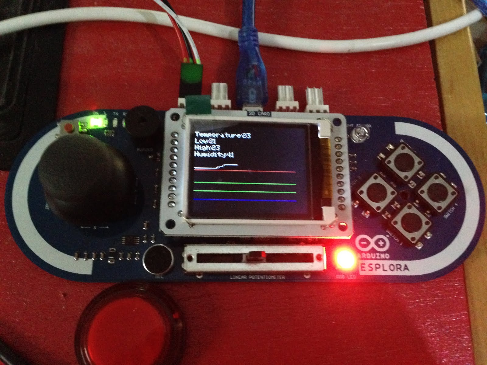

The TFT display on the Esplora is a really nice display. Unfortunately in some respects its too nice. Usually we use something like a Nokia5110 screen which is low resolution and each pixel is either on or off. Here we've got much higher resolution and full colour, which creates a real problem for us. With the smaller screens we can prepare the screen image in memory then push it out in a single blast, which minimises flicker. Here the screen is way to large to fit in the Arduino's minimal RAM, so we have to draw directly to the screen. Not only is this slower, but it means when we clear the screen to draw on it, the screen actually goes blank. Large amounts of flicker are unavoidable. To minimise it as best we can we're not going to clear the whole screen at once but rather clear off bits of it before redrawing:

make counter number
make minY number
make maxY number
when partialClear
.set displayColor to 000
.repeat (maxY-minY) using counter
..set displayY to minY-1+counter
..set displayX to 0
..tell display to "move"
..set displayX to 160
..tell display to "hfill"

when updateText
.set minY to 110
.set maxY to 118
.broadcast partialClear and wait
.set displayColor to 777
.set displayX to 0
.set displayY to minY
.set message to join "Temperature:" [temperature]
.tell display to "show"
.
.set minY to 100
.set maxY to 108
.broadcast partialClear and wait
.set displayColor to 777
.set displayX to 0
.set displayY to minY
.set message to join "Low:" [minTemp]
.tell display to "show"
.
.set minY to 90
.set maxY to 98
.broadcast partialClear and wait
.set displayColor to 777
.set displayX to 0
.set displayY to minY
.set message to join "High:" [maxTemp]
.tell display to "show"

The text is 8 characters high, so we use PartialClear to clear only the rows we're about to print on. Then we tell the screen to show the latest statistics.


when updateGraph
.set minY to (minTemp-graphOffset)*graphYscale-1
.set maxY to (maxTemp-graphOffset)*graphYscale+1
.broadcast partialClear and wait
.set displayColor to 007
.set displayY to (lowestThresholdTemp-graphOffset)*graphYscale
.set displayX to 0
.tell display to "move"
.set displayX to historyLength*graphXscale
.tell display to "hfill"
.
.set displayColor to 070
.set displayY to (lowThresholdTemp-graphOffset)*graphYscale
.set displayX to 0
.tell display to "move"
.set displayX to historyLength*graphXscale
.tell display to "hfill"
.
.set displayColor to 070
.set displayY to (highThresholdTemp-graphOffset)*graphYscale
.set displayX to 0
.tell display to "move"
.set displayX to historyLength*graphXscale
.tell display to "hfill"
.
.set displayColor to 700
.set displayY to (highestThresholdTemp-graphOffset)*graphYscale
.set displayX to 0
.tell display to "move"
.set displayX to historyLength*graphXscale
.tell display to "hfill"
.
.set displayColor to 777
.set displayX to 0
.set displayY to ((item 1 of history)-graphOffset)*graphYscale
.tell display to "move"
.repeat length of history using counter
..set displayX to counter*graphXscale
..set displayY to ((item counter of history)-graphOffset)*graphYscale
..tell display to "draw"

Finally we draw the graph, again using PartialClear to get rid of only the bit we need to. There are 4 horizontal lines on the graph, representing the 4 threshold temperatures, then we simply loop over "history" drawing the graph.

We placed this down in the cellars and were able to monitor temperature, and see how it varied. The graph was particularly handy, as it was able to reveal some large changes of temperature that happened when we weren't actually there.

As we had reservations about the accuracy of the Esplora's temperature sensor, we also attached a dht11 to on of the tinker kit outputs. Things still to do include logging data to the SD card, and sounding an alarm if the temperature gets to high - "quickly! To the Cheese Cave!!!!!"


Release 24: Flotilla, Esplora and Gameboy!

We try and keep Sniff releases lightweight and frequent, pushing out small updates once every month or so, but Release 24 got a little bogged down in its own awesomeness. It started out with some improvements to SniffPad to make the formatting a little clearer, but then we started work on something really exciting...

We ported Sniff so that it runs on GameBoy Advance! Not only did we port the basic code, and add graphics drivers but we ported the complete sprite library to run directly using the GBA's hardware sprites, so you can take games you've written using the "Hosted" version of the Sprite device, and they run with only minor modifications on a real commercial games console! If you've got a "Flash Cart" you can your run game on the real device, or you can just test in an emulator. We'll have a post in the next few days to document how to set everything up and get going.

The Gameboy work was going well, when the Flotilla arrived in the post... Super excited, we immediately got down to reverse engineering it, and got it running in Sniff. We've already done a few posts, and released a preview version of the Flotilla code, but its now integrated into this release. We've also added support for "Slider" and "Dial" - these are untested, as we don't have them yet, but they're simple enough that they should work.

As if that wasn't enough, we got our hands on an Arduino Esplora. This is technically the same as a Leonardo, so there wasn't any low level work to be done, but we've added an "Esplora" device which lets you read all of the sensors on the board in Sniff. Again we'll post details of this over the next week, but the code and examples are all included.

There are also a few more subtle tweaks and features we've added: We noticed in quite a few of the examples we were declaring variables which were essentially constants, but that we had to make them as numbers, then assign to them. Instead now you can assign a constant value to a number when you create it:

make gravity number 9.81
make maxWidth number 640

If you do this the value can never be changed. While this is slightly different to the way it works (for example) in C, but we think it makes more sense.

The other neat language feature is that you can now access command line args, so for example Sniffpad can take the name of a file to load:

make argv list of strings

when start
.if length of argv = 1
..set filename to item 1 of argv
.else
..set filename to "new"


As if that wasn't enough, as we were working on the GBA port, we refactored, and simplified the way the runtime handles ports, which should make the system more robust, and more portable in the future. You shouldn't notice this, though in the short term it might mean some of the more obscure ports are misbehaving. Let us know if you find any issues.

Wit that all behind us we can finally announce SNIFF RELEASE 24!

You can grab Release 24 from the Downloads page.

Thursday, 31 December 2015

The Esplora temperature sensor...

We got an Arduino Esplora for Xmas!! or more strictly a knock off copy. Official Esplora boards are way too expensive,  but copies are starting to appear, and for about £20 you can get a board, with a TFT screen included. We wasted no time getting everything working with Sniff, and we'll post details in a future post (once we've released the drivers in the next code batch). However its basically an Arduino Leonardo (use leo-sniff) with a bunch of sensors built into the board.

While overall we're fairly positive about the board, when we started coding for the temperature sensor, we ran into some problems, which might be of interest to others using the board.

The first thing we found was that readings were inconsistent and jumped around. A little research showed that this is a fundamental design problem with the Esplora.

The board uses a tmp36 and we can learn all about those from those helpful people at Adafruit. The great thing about the tmp36 is that it outputs a voltage dependant on temperature of between 0.2 and 1.75V over a range of -25 to 125 degrees. We can easily convert a given voltage to temperature using:

T=(1000V-500)/10

In other words the tmp36 is a solid, well thought out/built device that is well suited for many applications. However its inclusion in the Arduino isn't well thought out or well suited.

The AVR has a 10bit ADC, so when we apply a voltage to an analog pin we get an integer value:

A=(Vin/Vcc)*1024

Or to put it another way, our estimate of Vin is:

Vin=(A/1024)*Vcc

Dropping that in to the first equation gives:

T=Vcc*100*(A/1024)-50

and as Vcc is 5V

T=500*(A/1024)-50

which is exactly the equation you'll find inside the Esplora library. But here's the first real problem... What happens if we change A by 1? T changes by 500/1024 or about half a degree. The absolute  best we could hope for is that the temperature is going to change in half degree steps.

Now that would be OK in many cases - accurate to the nearest 1/2 degree over a range of -25 to 125 degrees is pretty impressive. The ds18b20 is a similar, or worse spec, and its great - I regularly drop it in coffee, or buckets of ice to see what happens. But the ds18b20 comes in a waterproof case on the end of a wire. The sensor on the Esplora is soldered to the board underneath the TFT screen. It's only going to measure air temperature in nice people friendly environments. Drop it in boiling water and you've got a bigger problem than half degree errors. Most of its life is going to between 20 and 25 degrees. Getting it wrong by 0.5 degrees is quite a lot when you'r only expecting a swing of 5 degrees anyway. Had the designers being paying attention to that graph on the Adafruit page they'd have noticed its got three lines on it, and the other two which represent the tmp34 and tmp35 are much steeper. In other words they give a bigger voltage swing for a given temperature change.With the tmp36, even in extremely hot or cold rooms we're never going to see more than a 0.1V swing, which the AVR ADC just isn't sensitive enough to measure well. They picked the wrong component for the job.

But things get worse... That half degree accuracy is only good if was assume our device is operating perfectly. A 10bit ADC might give you 10 bits of accuracy, but it probably won't. That last bit or two is going to wander around as it picks up noise from the surrounding circuits, so the reading jumps up and down by half a degree, essentially at random. Fortunately we can fix this by averaging the results. I averaged 10 results taken over 1 second and was able to get something fairly stable, and if the noise is truly random it can actually make the results a bit more accurate...

So wrote a demo app, averaging the temperature, which was reading a consistent 23 degrees and displaying it on the screen. Then I moved it to run from a USB PSU, rather than from the computer and the temperature reading dropped 5.5 degrees. Moving it back to the computer and it was high again. Moving it from the USB hub to being directly plugged in dropped it 5 degrees.

Going back to a previous version of our equation:

T=Vcc*100*(A/1024)-50

We simplified this using Vcc=5, because USB runs at 5V... except it doesn't. USB specifies a voltage between 4.75 and 5.25. There's always a margin of error, and its considered OK to have a value +-5%. That corresponds to a 5% swing in T+50, or about +- 4 degrees at room temperature.

Using a USB Voltage/Current meter I was able to measure my power sources, and found that my USB hub is borderline out of spec, giving a low voltage, and hence high temperature. Both the Mac port, and the USB battery are pretty close to being right on spec, but even the difference of 0.04V was enough to give a small change (after averaging).
USB hub: 4.7v 23.9C
Mac: 4.99v 18.8C
Battery 5.03V 18.3C

Unless you trust your power supply totally the sensor is accurate to with 4 degrees. Again that would be fine if we were measuring a range of temperatures, but as we're limited to measuring air temperature 4 degrees either way of a 22 degree reading is not knowing if its 18 degrees (put a jumper on) or 26 degrees (open a window).

At one point I was plotting the temperature on the screen and got a regular up/down cycle. It turned out my USB volt meter was dropping the voltage by a few mV every time it switched from volts to amps reading... enough to give a systematic temperature variation.

For reference I hooked up a dht11, and a ds18b20 to the tinker kit ports of the Esplora, and set it to display all three recorded temperatures. The DHT11 and ds18b20 produced different readings but they were consistent when I changed the power source. The DHT11 is known for being inaccurate, but if it constantly reads high (as mine seems to) then you can calibrate around it.


Now you might argue that its just a fun/toy beginners board and that it was built to a budget, but that doesn't hold water. For a start the official boards sell in kits for £70. Also while its pretty easy for me as an experienced engineer to deal with these issues, someone less experienced would just be sat with a gadget that didn't work reliably.

Perhaps the worst thing though is that there are other solutions out there that would do the job better and more cheaply. A tmp36 costs about £1 on eBay (pennies in bulk), but a thermistor costs pennies on eBay (decimal points in bulk). They provide similar accuracy but because you thermistors as a potential divider Vin is proportional to Vcc, which means that in the equations Vcc just cancels out.

The real ironic moment is when you realise they picked a component: the tmp36 that has as a design feature that Vout is independent to Vcc. The tmp36 behaves the same even if the voltage changes... which in this case directly leads to us getting the wrong results. It's not the tmp36's fault... They just picked the wrong component!

Monday, 28 December 2015

6 DOF Robot Arm Kit Assembly Instructions

As a Xmas treat for myself and the other robot lovers in the family, I recently bought a robot arm kit. Compared to things like the horrid Maplin robot arm the versions from China are relativity cheap, and remarkably substantial. They use six servo motors to drive them and can pick up some quite heavy stuff. Unfortunately they come without instructions... They arrive in the post as a bag of black metal brackets and bars with absolutely no indication of how they should be assembled. I've therefore made a particular effort do document the  build here,


The better servo's you can afford the better your arm will perform but as we need 6, and good quality servos can be expensive I chose to use MG996R's. I was able to get the six for under £20, and they have the distinction of using metal gearing. Most cheap servo's use plastic gears which aren't up to the task of moving a pretty heavy arm. If you feeling like experimenting you could use faster/plastic servos for the end of the arm (where strength is less important), and pay more for bigger/stronger servos at the base (where you need the strength), but to keep things simple I just ordered a batch of the single type.

The other extra compont I ordered was a set of metal servo horns. Servos come with a bunch of different shaped bits of plastic you can use to attach them to your hardware, but again we need something that's a bit stronger than usual. I read a post which recommended using these circular ones, and totally recommend the extra few pounds spent, rather than risk your build on some bits of plastic.

The other extra item you might not have that's going to really help this build along is a servo tester. These cost about £3 on eBay, and you just plug a battery in one side, and a servo in the other. Then turn the dial to move the servo, and check its range of motion. It also has a mode to move the servo to its centre position which is really handy when you're putting all this together.


I started by putting together the gripper. This is pretty easy, but there are couple of easy mistakes you can make - if you do it in the wrong order you'll not be able to fasten all of the screws.

Attach the horn to the wrist servo first, then attach it to the gripper.


Then mount the servo on the gripper, and attach the servo horn to the gripper. You should have something that looks like the above. Finally attach the servo horn to the servo: use the servo tester to move the servo fully counter-clockwise, then move the horn into place so that the jaws are closed. You can then test that the servo movement correctly opens and closes the arm before attaching the horn to the servo permanently. 

With this done you can now have some fun using the servo tester to control the gripper and pick things up. It's remarkably strong!


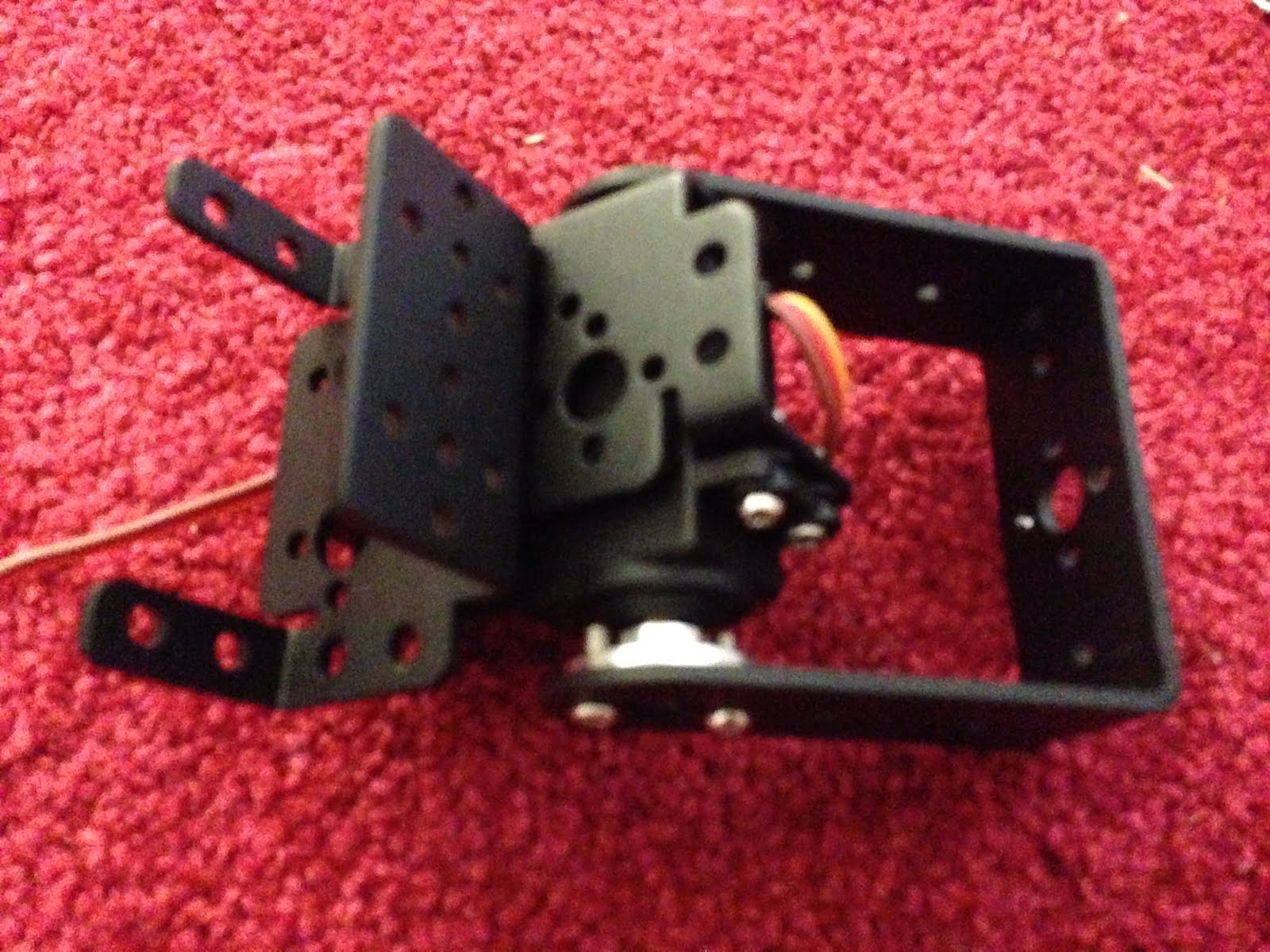
With the gripper completed we can work back down the arm. The above picture shows the beginnings of the joint assembly thats used for the three main joints on the arm. It consists of a U-bar and a servo bracket. What's less obvious is that they're bolted together with a bearing between them. Somewhere in the packaging you'll find what look like three fat washers, but infact they're bearings which are going to allow the joints to move smoothly.The bearing goes into the U-bar (from the outside) and then you can put a machine screw through from the inside (so the nut goes on the outside), The two pieces are secured together now but can still move freely.

You'll notice that there are a couple of short screws poking out from the servo bracket. You can use these to bolt on another bracket, which we'll put the write servo in. Make sure you use short screws as if they're too long you'll not get the servo to lie flat.


With that bolted on you can insert the servo and horn. You can get a better view from the other side:

Use the servo tester again to make sure that the range of travel is appropriate. Finally you can bolt the servo to the bracket, using the rubber grommets that probably came with your servo to keep everything nice and snug.


Here I've put the wrist servo and gripper into place to get an idea for what it will look like and check the range of movement again, but as the gripper and two servos are quite heavy, we'll leave final assembly till the end.

At this stage I turned my attention of the other end of the build - the base:


The base its quite easy to get started with. There are two larger "flat' u shapes that bolt together to make a platform. Then we bolt a servo bracket to this. A servo goes into the bracket, and then we add attach a second bracket to the servo horn so that we can spin this around.


This is a pretty horrid design. The only documentation I managed to find for one of these arms was a you-tube video, which used a base rotation mechanism like the other three joints, but oriented horizontally. One of the U-bars and a fourth bearing carry most of the lateral forces in that design, but here all the twisting load is on the axle of the servo. I suspect this servo isn't going to live too long. The older design also had a larger/heavier platform so was more stable. This one will need to be bolted to the floor. If possible see you can find a kit which uses the older design. [update: I added an extra set of brackets to support the base better]


Anyway... Working with what we've got, we use the top servo bracket as the basis for another joint, just like the one we built before. In the above pic the bearing is holding the next pair of u-bars in place (they're already bolted into an H). All we need to do next is insert the servo, and we've got a working base:


Now we just need to make the final join that connects the top to the base.
In this picture you can see the H we've just made, and a servo bracket attached to the top left arm (with a bearing again). The one piece left is an L shape which is attached to the back of the servo bracket and the botton of the other U-bar.

Here's a close up of the final joint, and the whole arm from the side, which gives a good idea of how everything goes together. All that's left is to bolt the wrist servo into its bracket and you've got a robot arm!!!


Use the servo tester to run all the parts through their range of motion. Hopefully you checked each joint as you built it to make sure that the servo was correctly centred. If it not quite right then you can try and make some adjustments now, but its tricky.

You'll find that un-powered the arm isn't strong enough to support its own weight, and it will keep collapsing. However powering up each joint will show that in fact its going to be pretty powerful. I guess you could use 6 servo testers(!!) to control the thing, but tomorrow I'll hook this thing up to an Arduino and we can start driving it properly!

Saturday, 19 December 2015

PCA9685 - lots of Servos and LED's with not many wires

We have a fairly predictable cycle of R&D here at Sniff Labs: It starts with us browsing Twitter, AliExpress and Ebay until we spot something cool. Then we get one, write a Sniff Device for it (if necessary), and code up up some demos. We do that for about a month, then push out a "Release". Once a release goes out, we do a blog post for each of the new features, explaining what it does and hopefully inspiring you to take it further...


In the release notes for the last release you'll not that we added support for "pca9685" boards... Then forgot to do the blog post so you've probably no idea what a PCA9685 board is! Well its a chip/board for controlling servos. Now you might say "what's the big deal?". Sniff can already drive servo's pretty easily:


make pulseTime number
when runServo
.forever
..set pulseTime to (1+x)*1000
..set servo to on
..wait pulseTime microsecs
..set servo to off
..wait 20 millisecs


This little snippet of code will drive a servo on a digital output pretty well. Just set "x" to be from 0 to 1 and the servo moves.

That's great if you're running one or two servos from an Arduino, but if you're running lots then the timing will probably start to drift, and you'll use a lot of CPU driving outputs when you could be doing more useful work. If you're on a Pi, then the timings will be a mess to start with, and you might want to be cautious of driving 5V servos from a 3.3v Pi. You should also be worried about output currents from the Pi. Finally you're using up output pins that you might need for something else.

The PCA9685  takes care of all of this: it uses i2c (only two wires), and drive 16 outputs with accurate timings. Breakout boards can typically drive an output output with a moderate amount of power, and you can run the outputs at a higher voltage than the control pins.

Connect up power, data and clock on the left and edge, then plug some leds or servos into the channels across the botton. The VCC pin on the left edge should be connected to the power supply that your controller uses (3.3v or 5v typically) while you provide power to drive the outputs with up to 6V from either the V+ pin or the screw terminals. If that's not enough you can connect the outputs on the right of the board to the inputs of the next board, and drive up to 64 boards with 16 servos on each!!! That's 1024 servos...


make i2c device
make pca9685 device
make pwmChannel number
make pwmValue number


Make a device, and we're ready to go. Lets start with some LED's:

#Channels 0-7 (that's how they're labeled on the board!)
#flash LED's
#Brightness goes from 0-1
when start
.make count number
.forever
..repeat 8 using  count
...set pwmChannel to count-1
...set pwmValue to (sin of (timer*100+count*10)) *0.5+0.5
...tell pca9685 to "set brightness"


Here the LED's are plugged into the first 8 channels of the board, which are numbered 0-7. Just set the channel, and a value between 0 and 1, then tell the pca968 to send that to the hardware. Here Ive set up a sine wave with an offset so we get a nice ripple effect.


#Channels 8-15 (that's how they're labeled on the board!)
#Move Servos
#Position goes from -1 to 1
#This corresponds to the "safe" 1-2mS pulse
#Your Servo may need or like a larger range
when start
.make count number
.forever
..repeat 8 using  count
...set pwmChannel to count+8-1
...set pwmValue to (sin of (timer*100+count*10))
...tell pca9685 to "set servo position"


Doing this with Servo's is just as easy. However the value goes from -1 to +1 and we use the command "set servo position". That's because servo's have some pretty specific timing requirements, so "set servo position" handles all that for you. Depending on your servos you might find that -1 to +1 doesn't give the full range of movement, in which case try increasing the range gradually. A lot of servos need a slightly larger range, but too wide a range of values can damage the servo. The -1 to +1 range is configured to be safe for most hardware, and follows the "standard" behaviour, but try experimenting.


Friday, 18 December 2015

Sniff and Flotilla

I recently posted that my Flotilla Medium starter kit had arrived, and I documented the low level code that you might find useful if you were going to write your own code to talk directly to the hardware. You could actually to that yourself entirely in Sniff using the serialPort device, but the plan was always to add Sniff devices to support the Flotilla.

I've now got those working, and you can download them and add them to an existing Sniff installation. Normally I'd release this as part of a full Sniff release, but it's getting close to Xmas, and I probably won't get a full release out until the new year. There's a particular cool feature that needs a little more work, so I'm holding off until that's fully working. In the mean time here are the files you need to try it out. The drivers (in the XHosted folder) need to be added to the lib/XHosted folder you already have. There are also some examples which I'll talk about now... [Update: as of R24 Flotilla support is included i the current release]

To compile the examples, use the normal "sniff" commands. On Unix platforms the Flotilla gets found the same way as an Arduino when you run "./setup". On Windows you'll need to explicitly tell it by typing:

export ARDUINODEV=COM4

or whatever port you have it on in the shell after you've run setup.


make flotilla device

make light flotillaLight device
make brightness number

when start
.forever
..tell light to "update"
..say join "Brightness:"[brightness]
..wait 1 secs


The first thing you need to do is make a flotilla device. This represents a the flotilla dock and much like the dock you don't actually need to do much with it. It just acts as a hub for all the other devices you might want to use.

Once you've got a dock you can make an actual module and do something with it. Here I've attached a light module, by making a flotillaLight device and calling it light. The Flotilla has 8 ports, but you can plug the module into any of them - Sniff will look for a light sensor and use whichever port it finds it on. However if there isn't one plugged in then it will give and stop your program.

Alternatively you can specify which port the module is plugged in to:
make light flotillaLight device 4

This has the advantage that if you've not plugged it in yet you'll get a warning message but your program will keep running, and you can plug the device into port 4 later. In future you'll also need to use this if you want to plug in multiple devices of the same type (the mega-treasure chest includes two light modules and two motors). At the moment you can only attach one of each type of module, but that'll be fixed before the full release.

To read or write a sensor, just tell it to "update". You can also tell the dock to update, which you might want to do if you're not updating any other sensors for a long time just to give it a chance to do any housekeeping work, but this generally shouldn't be necessary.

In the case of the Light sensor "update" sets the variable brightness and we just print it out.


make flotilla device
make thermometer flotillaWeather device
make temperature number
make pressure number


when start
.forever
..tell thermometer to "update"
..say join "temp :"[temperature]
..say join "pressure:"[pressure]
..say ""
..wait 1 secs


Weather works in the same way, setting temperature and pressure.

make flotilla device
make keypad flotillaTouch device 
make key1 boolean
make key2 boolean
make key3 boolean
make key4 boolean


when start
.forever
..tell keypad to "update"
..if key1
...say "1" 
..if key2
...say "2" 
..if key3
...say "3" 
..if key4
...say "4" 
..wait 0.1 secs

Touch sets the four variables to be true of false depending on if the button is pressed.


Rainbow is the most complex module in the Medium kit, and works just like the neoPixel device, except that we change the names.

make flotilla device
make rainbow flotillaRainbow device
make rainbowShade list of numbers
make rainbowColor list of numbers


rainbowShade is the brightness (between 0 and 100), while rainbowColor is the hue between 0 and 360. 

Rainbow Thermometer

Lets look at how we can use that to make "thermometer":

make flotilla device
make sensor flotillaWeather device 
make temperature number
make pressure number

make rainbow flotillaRainbow device
make rainbowShade list of number
make rainbowColor list of number


make counter number


when start
.repeat 5
..add 0 to rainbowColor
.
.forever
..tell sensor to "update"
..#say [temperature]
..
..delete all of rainbowShade
..set counter to 1
..repeat 5
...if counter*2+20<temperature
....add 10 to rainbowShade
...else
....add 0 to rainbowShade
...change counter by 1
..
..tell rainbow to "update"

We make a rainbow and a weather device, then fill the rainbowColor list with 0's representing red. Then we read the temperature, and fill in rainbowShade. Using counter, we calculate a value for each LED from 22 to 30 degrees. If the actually temperature is greater than that we turn the LED on (red). If its less than that we turn it off.

The result is a thermometer that displays temperatures from 20-30 degrees in 2 degree steps. This is a handy range as its easy to see the display change just by holding the sensor.

Altimeter

One of the neat things you can do with the weather sensor is measure altitude. We did this last summer using an Arduino and BMP180, but now we can do it with Flotilla. The code required virtually no changes - just swapping out the BMP180 for a flotillaWeather module:

make flotilla device
make sensor flotillaWeather device
make pressure number
make temperature number

make altitude number
make seaLevelPressure number
make seaLevelTemperature number

make message string

when start
.tell sensor to "update"
.set seaLevelPressure to pressure
.set seaLevelTemperature to temperature+273.15
.
.forever
..tell sensor to "update"
..broadcast calculateAltitude and wait
..set message to join "Temperature:" [ temperature ]
..say message
..set message to join "Pressure:" [ pressure*0.01 ]
..say message
..set message to join "Delta:" [ (pressure-seaLevelPressure)*0.01 ]
..say message
..set message to join "Altitude:" [ altitude ]
..say message
..say ""
..wait 1 secs


when calculateAltitude
.set altitude to seaLevelPressure/pressure
.set altitude to ln of altitude
.set altitude to altitude * 0.1903
.set altitude to e^ of altitude
.set altitude to seaLevelTemperature * (altitude-1)
.set altitude to altitude/0.0065


Check the original post for more details on this one. You might need a longer USB lead to get the most out of this example but its still pretty cool

Simon

Finally I wanted to do something with Touch, so I build a game of "Simon". The computer flashes the Rainbow LED's in a sequence which gets longer each turn, and you have to copy the patten on the keypad.

make flotilla device

make rainbow flotillaRainbow device
make rainbowShade list of numbers
make rainbowColor list of numbers


make keypad flotillaTouch device 
make key1 boolean
make key2 boolean
make key3 boolean
make key4 boolean

make pattern list of numbers

when start
.repeat 5
..add 0 to rainbowShade
.
.add 0 to rainbowColor
.add 120 to rainbowColor
.add 240 to rainbowColor
.add 60 to rainbowColor
.
.tell rainbow to "update"
.
.forever
..broadcast playGame and wait
..wait 5 secs

This is standard flotilla setup. Then we have a list called "pattern" that we're going to store the pattern so far in. We put four distinct colours in the rainbowColor list, but turn all the LED's off by setting their brightness to 0. Then we're ready to go...


make counter number
make led number

when playPattern
.set counter to 1
.repeat length of pattern
..set led to item counter of pattern
..replace item led of rainbowShade with 10
..tell rainbow to "update"
..wait 0.3 secs
..replace item led of rainbowShade with 0
..tell rainbow to "update"
..wait 0.1 secs
..change counter by 1


To play the pattern we  simply loop over the list turning on the required LED of a short period with a smaller time gap between each.

when playGame
.delete all of pattern
.forever
..add pick random 1 to 4 to pattern
..broadcast playPattern and wait
..
..set counter to 1
..repeat length of pattern
...set led to 0
...repeat until not led = 0
....if key1
.....set led to 1
.....wait until not key1
....if key2
.....set led to 2
.....wait until not key2
....if key3
.....set led to 3
.....wait until not key3
....if key4
.....set led to 4
.....wait until not key4
...if not led = item counter of pattern
....broadcast flash and wait
....stop script
...change counter by 1


To actually play the game we add a random led to the pattern so far then play it back. Now we need to check the the touch pad. We go through the pattern one step at a time and wait for a key to be pressed. We record the key press then wait for the key to be released.... This is important otherwise just touching one key would be recorded multiple times.

Then we check that the key pressed was the right one. If it wasn't we run a script called flash to indicate failure, and end the came. If we get to the end of the pattern then we go background, add another light to the sequence and keep going!


when start
.forever
..tell keypad to "update"
..set dummy to pick random 1 to 10
..wait 0.01 secs

You'll not that when I'm checking the buttons I'm not calling update. I need to keep calling it, otherwise the variables representing the keys will never change, but it would make the code messy, so instead I've got a separate script which just keeps calling update. (it also randomises the game by throwing away random numbers - I've talked enough about that in other posts).


when flash
.repeat 5
..delete all of rainbowShade
..repeat 5
...add 10 to rainbowShade
..tell rainbow to "update"
..delete all of rainbowShade
..repeat 5
...add 0 to rainbowShade
..tell rainbow to "update"

That just leaves flash which is pretty obvious.

Conclusions

And that's about it. So far I'm pretty impressed with the hardware. It's really nicely built, and the design allows for lots of expansion. Price wise its not cheap - the Medium kit with a dock and four modules is £39, but its not too bad. Based on the prices of the different sized starter kits I'd expect individual modules to cost between £5 and £10 (some costing more than others) when they become available. Many of the modules have arduino compatible equivalents that cost about £1, but that's from overseas suppliers. From a regular UK seller they'd cost about £4 so a couple of pounds extra to have something kid friendly and just plugs in and works is actually good value. For comparison LittleBits charge $18 for their temperature sensor!!! On the downside, having got the Medium kit up and running,  I want to do more with it than I can with just four modules, so I will need to get more modules...

Where the HW has real potential is for expansion. The design allows new modules to be added. There are currently 12 available, but I'm surprised the so called "pirates" at Pimoroni forgot to include a compass. A 16x2 LCD text screen would also be simple to add. Right now its a nice piece of fun, but wth an ever expanding range of modules at good prices, then this could be a really great piece of kit.