Sniff is a "Scratch-like" programming language that's designed to help Scratchers move gently from Scratch to more conventional languages. They can start writing programs, without having to learn a new language because Sniff is based on Scratch. They learn a little more about variables, compiling, syntax errors (!), and they can have fun controlling real hardware while they're doing it.
Showing posts with label Robot. Show all posts

Friday, 24 March 2017

Robot arm upgrades


One of the most popular posts on the Sniff blog is my documentation of the robot arm build - lots of people get the kits on eBay or aliExpress and then they arrive without any instructions. You literally get a bag of black metal shapes and some screws!


When I built the original I was careful to document everything I did, as even searching online there were no good instructions. However my research did reveal that there was a "better" kit out there, that had previously been sold, but that the kits currently being sold contained 1 less set of brackets/servo holders. As I noted in the original post, all of the weight and stress from the robot is carried by the base servo, which really isn't great.

It's fairly easy to find the brackets sold separately, so I bought an extra bracket, and finally got round to rebuilding the base of the arm. While the base servo is still taking a lot of the weight, its now supported by the bracket, spreading the stress around, and making the whole thing a lot more stable.


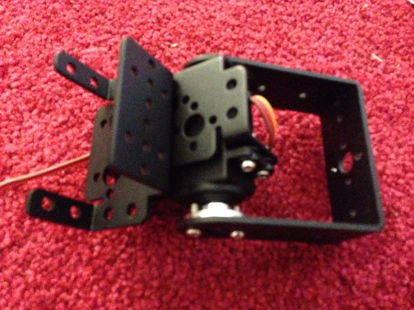
Here are some pics of the new base during assembly:


You can see that the base servo is removed from its original bracket, and placed in a new one, which is bolted to the old one... while this may seem redundant, it means there's now clearance underneath to attach a u-bracket around the whole servo.

The bracket for the next servo is connected essentially as before, but now the bolts connect the bracket to both the servo horn and the new u-bracket. That means when the arm's weight starts to tip itself over, that sideways force is transmitted (at least in part) to the bearing at the bottom, rather than being fully carried by the neck of the servo.

The result is much more stable. The extra metal work does place some restrictions on range of travel, but only in positions where the gripper would probably be crashing into the table anyway, So generally its looks like a good upgrade.

Friday, 23 September 2016

Receiving Lego IR

In the previous post, we used an IR LED to control Lego Power Functions motors, which was pretty useful, but what about going the other way - using a Lego PF remote to control an Arduino?

That standard Lego remote is really nice for controlling Robots as it has two levers, giving you forward/back tank style steering. There's a handy "reverse" switch for each lever, and best of all there's a channel selector, so you can operate up to four remotes at the same time. This is always a problem in workshops where everyone gets the same kit of parts, and everyones remote controls everyone else robots!

At about £7.50 from the Lego store, they're pretty reasonably priced if you're buying them for yourself, or even a classroom, though unfortunatly our workshop budget won't stretch to giving them away, as we do with the regular £1 remotes.

Lego uses a unique (but well documented) protocol, so which we've added to the regular receiveIR device, so if you have build a robot with an IR receiver you don't need to change anything, other than detect the new keypress codes.

Working with IR is cheap and easy - just get a  tsop-4828 receiver for about 50p, and wire it to a data pin on an Arduino (note that the transmit code should work on any micro controller, but the receive as some Arduino specific bits):


The code to read from an device, works exactly the same as it always did:

make remote receiveIR device D2
make irProtocol number
make keyPressed number

when start
.forever
..tell remote to "read"
..if not keyPressed = 0
...say join "Protocol:" [ irProtocol ]
...say join "KeyVal  :" [ keyPressed ]
...say ""

Now, if you point a lego transmitter at it you'll start getting key codes. The channel is returned in the variable irProtocal, so you can easily run multiple controllers at once. If you're really interested in making sense of keyPressed value then there's documentation available from lego. The value returned is the middle 2 nibbles of the data packet, with the escape bit tagged on the beginning.

While its possible to decode the packet based on the documentation, its probably easier to just look at the values that are being sent when each button/lever is pressed, and actual accordingly.

If we look at the codes sent by the regular remote, a value of 16 is sent when nothing is pressed. In fact you can subtract 16 from every received code and things start to make sense: Left stick generates 0 in the centre, 1 when forwards and 2 when backwards. Add these to the 16, that this remote always sends and you're in business. The right stick works the same except we multiple by four, so the value sent is 16+4*rightStick+leftStick.

Of course you can still use most other regular remotes to, but the Lego ones are a bit nicer. The code is now on live.sniff.org.uk along with an example and will by in the next desktop release.

Saturday, 30 April 2016

Driving Motors (from Microbit)

One thing I've always thought was pretty dumb was all the Raspberry Pi crowd building robot buggies using the Raspberry Pi - not because its a good thing to do, but because they think a Pi is the answer to everything! The Pi is a terrible boar to base a buggy around. It's expensive (comparatively), difficult to power, unreliable, and its actually just not very good at the task (lack of HW PWM, and timing reliability). The microbit however is ideal.

Kitronik sell a buggy kit for a £25 (plus £5 postage), but you can get the same motor, wheels, and a much nicer chasis for about about £7 on eBay. To make the cheap one work all you need is a motor driver board. They also sell one of those for £11.50 (its included in the buggy kit). It's a nice looking board. but you can get exactly the same functionality using a generic board which costs £1.50. The only catch is you will need a breakout board so you can hook stuff up to the microbit, (kitronik £4.50), but you'll need one of those anyway for other projects. It's also going to get a bit messy, so the Kitronik motor board is probably a good choice if you want an all in one solution, but if you've already got some motors, and a breakout then the £1.50 eBay motor driver is a great addition to your parts box.


This is the sort of board you want (eBay: Arduino motor driver). They can look a bit intimidating to hook up as theres lots of wires but they're pretty obvious.

Starting at the end, the screw terminals on the left and right are where the motors go. Just connect the two wires from the motor into a terminal pair and tighten them up. Don't worry about connecting them the right way - get it wrong and your motor runs backwards. You can either fix this in software, or just switch the wires around (in workshops the first thing I get kids to do once they've hooked up a motor is check its direction, and reverse wires if  necessary so everyone's idea of forwards is the same!).

The terminal block with three wires is marked (from left to right) 12v, Gnd, 5V. Don't worry that we won't be operating at these voltages... 12v is a maximum(ish). If you're using the "yellow" motors, then they can run up to about 6v, so connect a power source/batteries of 5-6v between the left input, and to the Ground pin. The left pin provides power to the motors, but it also provides a lower voltage supply to the rest of the electronics on the board - that's what the 5V is for. If you're using a microbit DO NOT CONNECT ANYTHING ELSE TO 5V!

That's the heavyweight side hooked up - now to look at the controller side:


There are four pins on the board labeled in1-in4. (There are also a couple of pins labeled en-A and en-B butthey should have jumpers on them, and we can ignore them) - these need to be connected to four output pins on the Microbit. If you just want to control one motor you could connect them with croc-clips to D0 and D1, but i'm using the MB^5 (MicroBit Breakout Board Breakout Board) I build in the last post. It exposes pins 13-16 as a row of headers which is perfect for this. I just connected them straight across. You could connect them straight to a regular microbit breakout board - you'll just spend more time counting/checking pins. You'll also note there's also a ground connection from the boards GND pin to the 0V pin on the Microbit. DO NOT ATTEMPT TO CONNECT POWER BETWEEN THE BOARDS... you'll destroy your Microbit.

With that in place we're read to do some software:

make m1fw digital output D13
make m1bw digital output D14

when start
.forever
..set m1fw to yes
..set m1bw to no
..wait 1 secs
..set m1fw to no
..set m1bw to yes
..wait 1 secs

Here I've set up a single motor. Microbit pins 13/14 are connected to in1,in2 of the motor board, which control out1/out2 which are connected to what we'll call motor 1.

Driving a motor using two pins can be a bit confusing, but a little creative variable naming goes a long way. I've called the two output m1fw and m1bw: motor 1 forwards and backwards. So to go forwards, set m1fw to yes, and m1bw to no. To go backwards m1fw is no, and m1bw is yes. To stop you set them both to no (or set them  both to yes if you want, but no make more sense).

We could do the same for motor 2, but we can be a bit more clever.

make m2fw analog output D15
make m2bw analog output D16
make speed number
when start
.forever
..set speed to sin of (timer*100)
..if speed>0
...set m2bw to 0
...set m2fw to speed
..if speed<0
...set m2fw to 0
...set m2bw to -speed
..wait 0.1 secs

If you remember when we flashed an LED we used an analog output to flash the LED very fast, and it looked like it was dimming. We can use the same trick to control the speed of our motor. Pins 15/16 are driving in3/4 on the board. I've created a variable called "speed", which I set to something between -1 and +1, which are going to represent full reverse and full forwards. I use a Sin wave just to create something interesting.

If speed is positive we want to go forwards, so set m2bw to 0, and m2fw to how fast we want to go forwards. If we're going backwards, then M2fw is 0, and m2bw to -speed (because speed is negative, so -speed is how fast we go backwards).

The "turning on and off fast" can break if we try and change the speed to often, so we add a 0.1 second delay in there just to keep things running smoothly. If I was using this in a bigger program I might write an update motor script to handle all of this and make everything a bit cleaner:


make speed number
when updateMotor
.if speed>0
..set m2bw to 0
..set m2fw to speed
.if speed<0
..set m2fw to 0
..set m2bw to -speed

when start
.forever
..set speed to sin of (timer*100)
..broadcast updateMotor
...wait 0.1 secs

If you like you can even write it as:

make m2fw analog output D15
make m2bw analog output D16
make speed number
when start
.forever
..if speed>0
...set m2bw to 0
...set m2fw to speed
..if speed<0
...set m2fw to 0
...set m2bw to -speed
..wait 0.1 secs

when start
.forever
..set speed to sin of (timer*100)


While this isn't the most efficient system it is the most "scratch-like". We've got one script updating the motor speed every 1/10th of a second, so the "main" program at the bottom can just do its thing, and set the speed it would like the motor to be running at, without worrying about how that happens.

Hopefully as the microbit ecosystem matures we'll see a whole range of cheap boards but there's a whole load out of bits on ebay already that are easy to hook up once you've got some kind of breakout.

Monday, 28 December 2015

6 DOF Robot Arm Kit Assembly Instructions

As a Xmas treat for myself and the other robot lovers in the family, I recently bought a robot arm kit. Compared to things like the horrid Maplin robot arm the versions from China are relativity cheap, and remarkably substantial. They use six servo motors to drive them and can pick up some quite heavy stuff. Unfortunately they come without instructions... They arrive in the post as a bag of black metal brackets and bars with absolutely no indication of how they should be assembled. I've therefore made a particular effort do document the  build here,


The better servo's you can afford the better your arm will perform but as we need 6, and good quality servos can be expensive I chose to use MG996R's. I was able to get the six for under £20, and they have the distinction of using metal gearing. Most cheap servo's use plastic gears which aren't up to the task of moving a pretty heavy arm. If you feeling like experimenting you could use faster/plastic servos for the end of the arm (where strength is less important), and pay more for bigger/stronger servos at the base (where you need the strength), but to keep things simple I just ordered a batch of the single type.

The other extra compont I ordered was a set of metal servo horns. Servos come with a bunch of different shaped bits of plastic you can use to attach them to your hardware, but again we need something that's a bit stronger than usual. I read a post which recommended using these circular ones, and totally recommend the extra few pounds spent, rather than risk your build on some bits of plastic.

The other extra item you might not have that's going to really help this build along is a servo tester. These cost about £3 on eBay, and you just plug a battery in one side, and a servo in the other. Then turn the dial to move the servo, and check its range of motion. It also has a mode to move the servo to its centre position which is really handy when you're putting all this together.


I started by putting together the gripper. This is pretty easy, but there are couple of easy mistakes you can make - if you do it in the wrong order you'll not be able to fasten all of the screws.

Attach the horn to the wrist servo first, then attach it to the gripper.


Then mount the servo on the gripper, and attach the servo horn to the gripper. You should have something that looks like the above. Finally attach the servo horn to the servo: use the servo tester to move the servo fully counter-clockwise, then move the horn into place so that the jaws are closed. You can then test that the servo movement correctly opens and closes the arm before attaching the horn to the servo permanently. 

With this done you can now have some fun using the servo tester to control the gripper and pick things up. It's remarkably strong!


With the gripper completed we can work back down the arm. The above picture shows the beginnings of the joint assembly thats used for the three main joints on the arm. It consists of a U-bar and a servo bracket. What's less obvious is that they're bolted together with a bearing between them. Somewhere in the packaging you'll find what look like three fat washers, but infact they're bearings which are going to allow the joints to move smoothly.The bearing goes into the U-bar (from the outside) and then you can put a machine screw through from the inside (so the nut goes on the outside), The two pieces are secured together now but can still move freely.

You'll notice that there are a couple of short screws poking out from the servo bracket. You can use these to bolt on another bracket, which we'll put the write servo in. Make sure you use short screws as if they're too long you'll not get the servo to lie flat.


With that bolted on you can insert the servo and horn. You can get a better view from the other side:

Use the servo tester again to make sure that the range of travel is appropriate. Finally you can bolt the servo to the bracket, using the rubber grommets that probably came with your servo to keep everything nice and snug.


Here I've put the wrist servo and gripper into place to get an idea for what it will look like and check the range of movement again, but as the gripper and two servos are quite heavy, we'll leave final assembly till the end.

At this stage I turned my attention of the other end of the build - the base:


The base its quite easy to get started with. There are two larger "flat' u shapes that bolt together to make a platform. Then we bolt a servo bracket to this. A servo goes into the bracket, and then we add attach a second bracket to the servo horn so that we can spin this around.


This is a pretty horrid design. The only documentation I managed to find for one of these arms was a you-tube video, which used a base rotation mechanism like the other three joints, but oriented horizontally. One of the U-bars and a fourth bearing carry most of the lateral forces in that design, but here all the twisting load is on the axle of the servo. I suspect this servo isn't going to live too long. The older design also had a larger/heavier platform so was more stable. This one will need to be bolted to the floor. If possible see you can find a kit which uses the older design. [update: I added an extra set of brackets to support the base better]


Anyway... Working with what we've got, we use the top servo bracket as the basis for another joint, just like the one we built before. In the above pic the bearing is holding the next pair of u-bars in place (they're already bolted into an H). All we need to do next is insert the servo, and we've got a working base:


Now we just need to make the final join that connects the top to the base.
In this picture you can see the H we've just made, and a servo bracket attached to the top left arm (with a bearing again). The one piece left is an L shape which is attached to the back of the servo bracket and the botton of the other U-bar.

Here's a close up of the final joint, and the whole arm from the side, which gives a good idea of how everything goes together. All that's left is to bolt the wrist servo into its bracket and you've got a robot arm!!!


Use the servo tester to run all the parts through their range of motion. Hopefully you checked each joint as you built it to make sure that the servo was correctly centred. If it not quite right then you can try and make some adjustments now, but its tricky.

You'll find that un-powered the arm isn't strong enough to support its own weight, and it will keep collapsing. However powering up each joint will show that in fact its going to be pretty powerful. I guess you could use 6 servo testers(!!) to control the thing, but tomorrow I'll hook this thing up to an Arduino and we can start driving it properly!

Friday, 9 October 2015

Inverse Kinematics (IK) for your Robot Arm

A basic robot arm has a number of segments of (usually) fixed length. Between each of these is a joint which can rotate. We move the arm by changing the angles at each of the joints. If we know the length of each segment, and the angles then we can start at the base of the robot, and calculate the position of the end of the arm:

when getEndOfSegementPosition
.make count number
.set displayX to 0
.set displayY to 0
.set angle to 0
.
.repeat segementNumber using count
..change angle by item count of segementAngles
..change displayX by item count of segementLengths * cos of angle
..change displayY by item count of segementLengths * sin of angle


This is called Forward Kinematics or FK, and its also used in computer animation to position and draw a characters limbs. It's provides complete, precise control. However its also a bit slow and tedious. If we want a character (robot arm) to press a button, then we need to mess around with all of the angles until we get the hand in the right place.

Wouldn't it be easier if we could just tell the computer where we want the end of the arm to be, and let it figure out all the necessary angles for us? This is Inverse Kinematics, as we're calculating the required input from the desired output (whereas in FK we apply the inputs to see the output - forwards!).


If your arm only has one or two joints then you can perhaps work this out analytically (using maths!), but if you're arm is lots of segments, then finding the best set of angles for all of them becomes tricky. Especially as there are likely to be many possible sets of angles that would all get the same result. 

One commonly used way of tackling the project is to use Cyclic Coordinate Descent (CCD):
[WELMAN C.: Inverse Kinematics and Geometric Constraints for Articulated Figure Manipulation. Master’s thesis, Simon Fraser University, 1989] . This works well, and is simple enough to implement that we can do it in Sniff.

We look at a joint somewhere along the arm and consider the position of the end effector, compared to the target. We then rotate that joint to minimise the difference between the current position and the desired position of the end effector. Because we can only move one joint, the optimal angle for the joint is always to orient the arm so that the vector from the joint to the end effector is pointing towards the target. When the desired and actual locations line up then we've done the best we can with that single joint.
Lets try that again. Consider joint B. We'd like to move C to T, but the best we can do is C'.

make jointNumber number
when updateJoint
.make sX number
.make sY number
.make dX number
.make dY number
.make desiredAngle number
.make actualAngle number
.make deltaAngle number
.
.set segementNumber to jointNumber - 1
.broadcast getEndOfSegementPosition and wait
.set sX to displayX
.set sY to displayY
.
.set dX to mouseX-sX
.set dY to mouseY-sY
.set desiredAngle to atan of (dY/dX)
.
.set segementNumber to length of segementLengths
.broadcast getEndOfSegementPosition and wait
.set dX to displayX-sX
.set dY to displayY-sY
.set actualAngle to atan of (dY/dX)
.
.set deltaAngle to desiredAngle-actualAngle
.
.set angle to item jointNumber of segementAngles
.change angle by deltaAngle
.if angle >90
..set angle to 90
.if angle <-90
..set angle to -90
.replace item jointNumber of segementAngles with angle

To do that in Sniff, we just get the end of the previous section (the position of the joint), find the vector to the target, and calculate the desiredAngle. Then we do the same, but using the end position of the arm to find the actualAngle. Calculate the difference and add it to the angle of this joint.

You'll notice that there's some code to stop angle being greater or less than 90 degrees - this is a constraint. One of the neat bits about this approach is that its really easy to tweak it, in this case to prevent the arm bending more than 90degrees at any single joint but we could have different constraints for each joint, or contain deltaAngle so that it can't move to quickly.

Of course its quite likely that we can't get to correct position by moving just one joint, so we apply this adjustment to each joint in turn:

...set jointNumber to length of segementLengths
...repeat length of segementLengths
....broadcast updateJoint and wait
....change jointNumber by -1

However note that we start at the end of the arm, and move back to the root. Intuitively you can think about reaching for something: you move your wrist first, and only move your whole arm from your shoulder when finer motions can't to the job.

Typically you'd apply this whole process a few and the arm will end up pretty much where its supposed to be!

Try it!!! The full code will be in the next release of Sniff.

The code works pretty well for a basic implementation, but it has a few glitches. Tweaking the constraints can dramatically help the quality of the final position. However the main issue is that we're using the atan function to calculate an angle from the ration of dy/dx. While its certainly true that tan(theta)=dy/dx its less clear cut that theta=atan(dy/dx). This can break, not only because dx might be zero, but also because it assumes that we're working positive numbers. We can't tell the difference between 4/5 and -4/-5 because they're the same, but the required angles are 180 degrees out!! In C we'd use atan2(y,x) which does the divide for itself, so it works reliably for all angles. The full code includes an implementation of atan2, which makes everything nice and stable.

For a real arm we might also want to do the whole thing in 3D, which is much harder, but if you've got one of the simple USB robot arms, then they only support pivoting at the base and at the grabber. The main body of the arm remains in a 2D plane. You can therefore calculate the rotation of the base required to place the target in the plane of the arm, then treat the rest as a 2D problem. I've not got one of these but it should simple to adapt this code to control one.

Tuesday, 15 September 2015

E-Compasses revisited

We've had support for the hmc5883 magnetometer for some time. This measures the magnetic field strength on 3 axis, which with a little bit of trigonometry can be turned into a compass. We used this on SniffBot so that it could be instructed to face North when in idle mode. This worked brilliantly sometimes, but a few times we tried it, it just behaved very badly. We put this down to the generally messy magnetic field caused by all the metal and electronic equipment we have around here.

However we were prompted to revisit it, by the announcement of the BBC Microbit. Despite this being promised to arrive in schools in the next few weeks, no one has yet seen one... slightly worrying. However we do know it includes a mag3110 magnetometer. This does exactly the same job as the hmc5883, and in fact they both run on i2c, so for all practical purposes its a direct drop in replacement. So in Sniff R21 we've added support for the mag3110. With the new driver you should be able to just change:

make magnetometer hmc5883 device

To:

make magnetometer mag3110 device

And you're good to go.

When we tried it, we found that the results were pretty unreliable, but a bit of research suggested we could improve things by calbrating the sensor. If you've got an iPhone and used the compass app, then you'll be familiar with this, where it asks you to wave the phone around. The problem is that the chip tends to be biased, outputting the results with a fixed offset.

From our experience (sample size 1) on the hmc5883 this is sometimes quite a small error, so we got OK results... sometimes! On the mag3110 this is typically quite a larger error so we need always need to compensate for it.

While your phone does some complex stuff, including using the accelerometer to track the movement of your phone during calibration, we can do a basic calibration by getting you to wave the chip around. If you move it enough we'll get max and minimum values on each axis which are Offset+field, and Offset-field. Taking the average gives is the offset, which we can then subtract from subsequent readings.

To make this happen we've added a new variable compassCalibrate. If you set it to "yes" then you can  still use the compass as normal but the readings are also used for calibration. Provided you're operating in a relatively constant magnetic field, this works really well, so if you just need a generic compass just set it to "yes".

when start
.set compassCalibrate to yes
.
.say "Calibrating"
.repeat 100
..tell magnetometer to "read"
..wait 0.1 secs

In the compass.sniff example code, we set compassCalibrate to yes, then take 100 readings over 10 seconds to get a baseline calibration. During this time you should turn the chip around as much as possible. However even after we leave this setup phase, and start collecting "real" readings, we leave calibration on, and in fact the accuracy does seem to improve with further use.

.forever
..tell magnetometer to "read"
..say join "Heading " [ heading ]
..say ""
..wait 1 secs

Where this approach will fail is if you actually want to measure a changing magnetic field. Large changes in the field will be partially calibrated out, as the sensor tries to correct for something it actually should be measuring. In which case you should probably calibrate initially in a constant field, then turn calibration mode off.

With this code in place the Mag3110 worked really well, so we went back and added the same calibration modes to the Hmc5883. Your old code should work just as it always did, but if you add a calibration phase, or simple let the device calibrate as you're using it you should see much better results.

Sunday, 22 March 2015

Race Control

I've been running an Arduino robot workshop for the last few weekends, and next week is the final session. So far the kids have done a great job, and have build and coded IR controlled robots similar to SniffBot Jr. This design is well suited to the task, as its cheap enough that the cost of the session can cover the components, and everyone gets to take their robot home at the end (I've seen ads for some pretty expensive workshops where the students projects go back in the parts bin at the end of the week - I think the kids would be devastated to have to give their creations back!).

For the final week I want to set them some challenges so they can race their robots against each other. However as they've all got the same IR controllers the events will have to be time trials: a salom/obstacle course, sumo against some smaller bots, and finally an all out race around a track. I could just time each event on a stopwatch (phone!), but I thought I'd so something more fun.

I happened to have an Arduino Uno and some Neo Pixels attached to a sheet of perspex, so I realised I could turn that in to a great "race control"/starting mechanism and timer. In motor racing, races are started by 5 lights lighting up red one at a time. The lights then hold for a few seconds (randomised) before turning off to signify the start of the race.

That would be pretty easy to build, but I had a lot more neoPixels and just lighting them up red would be a bit boring, so I chose to light them yellow to signify the ready state. I'd then press a button, and the yellow lights would turn red in sequence. Once they were all red, they'd hold for a random time before turning green to start the race. That would also start the timer. On pressing the button again the timer would stop and the lights would display something colourful to celebrate the end of the race.


To code that we start by defining the hardware:

make neoPixel ws2811 device A1
make neoColor list of number
make neoShade list of number

make lcd device
make displayFlush boolean

make message string

make button analog input A0

make ledCount number
make startTime number
make index number

The NeoPixels are attached to A1 using a sensor shield. Depending on the version you have, one of the neat features is that it breaks out A0-5 around the edge, so that even when you have another shield on top you can still get to the Analog pins.

For the timer display I use an "LCD Shield". These are available everywhere, and there are dozens of different brands, but they're all the same. They're support cheap, and are far easier than wiring up a regular LCD (which I've never even tried - either use a shield or get an i2c LCD which just uses two pins but is slower to refresh). The only gotcha is that there's a design fault on many of them - just never use pin 10 for anything and you'll be fine! There are 5 buttons plus a reset, but rather than using 5 pins they're attached via resistor network to A0. Each button returns a different analog value. 

I could have used something like an Embedded Adventures 7 segment display, or even one of their larger displays, but then it would have needed a bit more "construction". the LCD shield just plugs in and is pretty robust.

when start
.set ledCount to 16
.repeat ledCount
..add 60 to neoColor
..add 50 to neoShade
.tell neoPixel to "show"
.
.tell lcd to "clear"
.set message to "ready"
.tell lcd to "show"
.
.wait until button< 0.8


Step 1 is to load up the neoPixel colour and shade array with 60 to mean yellow and a brightness of 50 which means full brightness/saturated colour. For testing you can drop this down to around a 10 - it's easier on the eyes! Once loaded we call "show" to write the values to the pixels.

.wait until button< 0.8
.
.tell lcd to "clear"
.set message to "set"
.tell lcd to "show"
.
.repeat ledCount using index
..replace item index of neoColor with 0
..tell neoPixel to "show"
..wait 0.2 secs

Now we wait for a button to be pressed. We don't care which button so just wait till the value drops below 0.8. Then clear the LCD and display the message "set".

We now need to turn each pixel red in turn. I've used the "new" repeat using syntax as I find it really helpful - the code is the equivalent of:

.set index to 1
.repeat ledCount
..replace item index of neoColor with 0
..tell neoPixel to "show"
..wait 0.2 secs
..change index by 1

But its a little clearer once you're up to speed with it. For younger children just transitioning from Scratch you should probably stick with the version they recognise, and then once they've got the idea of it you can introduce the "short cut".

.wait (pick random 5 to 30)*0.2  secs
.
.delete all of neoColor
.repeat ledCount
..add 120 to neoColor
.tell neoPixel to "show"

Once all the lights are red we wait for a random time between 1 and six seconds before switching the lights to green. We could have done this as we did for the previous code with an index counter, but its easier to throw them all away and replace them all.

.set startTime to timer
.
.repeat until button < 0.8
..tell lcd to "clear"
..set message to [timer - startTime]
..tell lcd to "show"
..wait 0.1 secs
.

So now we're racing, so record the start time, and loop until the button is pressed again to finish the race. Each time around the loop we update the screen with the new elapsed time. We need a bit of a delay so that the screen isn't too flickery - we don't want to clear it just after we've displayed the message! 0.1 seconds is faster than I can press the stop button so don't mind the timing error this might introduce.

The LCD screen will already be displaying the final time, so there's no need to update it any more. All that's left is do make the neoPixels look pretty:

.
.forever
..set index to timer*10
..delete all of neoColor
..repeat ledCount
...add ((index mod ledCount)*2/ledCount)*360 to neoColor
...change index by 1
..tell neoPixel to "show"


Potentially we could put all this code in a loop to time multiple races, but there's a reset button on the shield which starts the program again, so its easier to just use that.

This was never meant to be example code, or used as a classroom exercise - it was just something cool that I thought would make the robot race more fun, but now its done I realise that actually it's a pretty great project for a short workshop. It would also run really well (without the timer) on the 4tronix smart badge I just got...

Monday, 11 August 2014

Studuino

At Scratch@MIT2014 Arduino was a big thing - lots of people controlling Arduino's from Scratch (though of course only Sniff lets you actually program the Arduino!). The most visible of those groups was a large contingent from ArTeC - a Japanese company that make and sell robot contraction kits. They use a strange block mechanism that clicks together, like some strange and alien lego. They have motors and sensors to plug into those blocks. They're pretty cool, and they had some great demo robots made from the things.

To control these robots the have their own custom Arduino clone, which they call the Studuino. They were selling these at the conference for $3 - in other words they were giving them away (regular price is $30), but didn't want the first guy who turned up at their stand to take all of them. As it turns out the first guy at the stand was me, and I grabbed two!


It turns out that these are as strange as they look. The good things about them are that they're about the size of an Uno, and have standard(ish) Arduino socket layout. I say standard-ish, as the ICSP port is moved. This isn't a biggy, but it means some shields that use SPI won't work. For controlling robots, all of the i/o pins (A & D) are broken out on gnd/Vcc/Signal three pin servo headers. We like this a lot, as it makes plugging in things really easy. However the "feature" of the board is that it has two motor drivers built in, and four buttons. ArTeC's robot components will plug straight in, and they make a  really nice box that attaches the board to their block system.

So what are the downsides: The main on is that it uses an ATmega168pa which has only 16K ROM, and 1K RAM - half the specification of an UNO. It runs at 8MHz (half the speed of an UNO), though that's probably a good thing if you're running of battery, as it will save power. The whole thing operates at 3.3V which in theory is better (and again saves power), but in practise the whole 5v/3.3v arduino thing is a bit of a mess. Operating at 3.3V means you need to be a bit more careful. What all this comes down to is its going to suffer from the "not an UNO" effect: They UNO board is so prolific, any differences make it harder to work with, as everyone supports the UNO, and writes tutorials assuming that's what you're using. This isn't ArTeC's fault - Arduino's own Due is the biggest victim of the effect, but its a hassle in a board that's obviously aimed at beginners. There's a 3.3V/5V jumper on the Studuino, but it doesn't switch the whole  board over - its exact operation is unclear.

Another niggle with the board is that it uses a pl2303 USB chip, so you'll need to install drivers. The UNO and other boards which use the 16u2 to provide USB, work out of the box on Mac, but you need to install a driver to use the Studuino. There are links and instructions on the ArTeC site, or you can get the driver direct from the manufacturer.

As with most non-standard boards you need to make a few tweaks to the standard Arduino installation. Again ArTeC include instructions for installation. However you don't need those if you just want to use the Studuino with Sniff (or for that matter with Scratch - they provide a mod'ed version of Scratch too).

Plugging in and running Sniff setup detects the board fine (at least on Mac - let me know how you get on, on other platforms). If it doesn't check that there's a file: /dev/ttyXXX which shows that the driver is working correctly.

Running Sniff requires a few tweaks to the standard uno-sniff, and in the next release there'll be a stud-sniff. However to let you get started there's a zip file you can download which contains all of the extra's you need to add to the current Sniff release. Add stud-sniff to the Sniff/bin folder.

You should now be able to compile and install standard Sniff programs using stud-sniff. Try running blink from the Sniff/examples/Arduino folder:

stud-sniff blink.sniff

and the green light on the board should start blinking.


The Studuino's buttons are a nice touch - when I first got an Arduino, I was frustrated that there were button press examples, but no button on the board. Combined with the standard onboard LED, having a few buttons is a great help for beginners. The buttons are connected to A0-A3, but provided you don't press the buttons you should still be able to use those pins as you normally would.

make studuino studuinoButtons device
make buttonA boolean
make buttonB boolean
make buttonC boolean
make buttonD boolean

make led digital output 13

when start
.forever
..tell studuino to "checkButtons"
..if buttonA
...set led to off
..if buttonB
...set led to on

To use the buttons from Sniff, use the studuinoButtons device (it takes care of pull-ups, which Sniff normally doesn't), and tell the studuino to checkButtons. You can then use the state of bottonA-D to do whatever you like.

The Motor driver uses pins D2,3,4,5,7 & 8. In theory you should be able to use these for other tasks if you don't need the motors, but its probably best to avoid them if possible. It's perfectly possible to drive these directly from Sniff, but to simplify things (and make the code comparable with the standard Motor Shield), theres another device:

make buttons studuinoButtons device
make buttonA boolean
make buttonB boolean
make buttonC boolean
make buttonD boolean

make motors studuinoMotors device
make motor1 number
make motor2 number

when start
.forever
..tell buttons to "checkButtons"
..if buttonA
...set led to off
..if buttonB
...set led to on
..
..set motor1 to 0
..if buttonC
...set motor1 to 1
..if buttonD
...set motor1 to -1
..tell studuinoMotors to "update"
..
..wait 0.1 secs

Originally I set this up as a single device for both buttons and motors, but separating them is more flexible, and makes them more compatable with other Sniff programs.

Overall the Studuino is a nice board, with a couple of handy features, though it suffers from simply not being an Uno. The smaller CPU probably isn't a problem it you're just making simple robots, and if you're working with ArTeC's other products, then its great.

You can download all the bits you need to get started here. We'll add these to the next release. Let us know how you get on...