Sniff is a "Scratch-like" programming language that's designed to help Scratchers move gently from Scratch to more conventional languages. They can start writing programs, without having to learn a new language because Sniff is based on Scratch. They learn a little more about variables, compiling, syntax errors (!), and they can have fun controlling real hardware while they're doing it.

Monday, 28 December 2015

6 DOF Robot Arm Kit Assembly Instructions

As a Xmas treat for myself and the other robot lovers in the family, I recently bought a robot arm kit. Compared to things like the horrid Maplin robot arm the versions from China are relativity cheap, and remarkably substantial. They use six servo motors to drive them and can pick up some quite heavy stuff. Unfortunately they come without instructions... They arrive in the post as a bag of black metal brackets and bars with absolutely no indication of how they should be assembled. I've therefore made a particular effort do document the  build here,


The better servo's you can afford the better your arm will perform but as we need 6, and good quality servos can be expensive I chose to use MG996R's. I was able to get the six for under £20, and they have the distinction of using metal gearing. Most cheap servo's use plastic gears which aren't up to the task of moving a pretty heavy arm. If you feeling like experimenting you could use faster/plastic servos for the end of the arm (where strength is less important), and pay more for bigger/stronger servos at the base (where you need the strength), but to keep things simple I just ordered a batch of the single type.

The other extra compont I ordered was a set of metal servo horns. Servos come with a bunch of different shaped bits of plastic you can use to attach them to your hardware, but again we need something that's a bit stronger than usual. I read a post which recommended using these circular ones, and totally recommend the extra few pounds spent, rather than risk your build on some bits of plastic.

The other extra item you might not have that's going to really help this build along is a servo tester. These cost about £3 on eBay, and you just plug a battery in one side, and a servo in the other. Then turn the dial to move the servo, and check its range of motion. It also has a mode to move the servo to its centre position which is really handy when you're putting all this together.


I started by putting together the gripper. This is pretty easy, but there are couple of easy mistakes you can make - if you do it in the wrong order you'll not be able to fasten all of the screws.

Attach the horn to the wrist servo first, then attach it to the gripper.


Then mount the servo on the gripper, and attach the servo horn to the gripper. You should have something that looks like the above. Finally attach the servo horn to the servo: use the servo tester to move the servo fully counter-clockwise, then move the horn into place so that the jaws are closed. You can then test that the servo movement correctly opens and closes the arm before attaching the horn to the servo permanently. 

With this done you can now have some fun using the servo tester to control the gripper and pick things up. It's remarkably strong!


With the gripper completed we can work back down the arm. The above picture shows the beginnings of the joint assembly thats used for the three main joints on the arm. It consists of a U-bar and a servo bracket. What's less obvious is that they're bolted together with a bearing between them. Somewhere in the packaging you'll find what look like three fat washers, but infact they're bearings which are going to allow the joints to move smoothly.The bearing goes into the U-bar (from the outside) and then you can put a machine screw through from the inside (so the nut goes on the outside), The two pieces are secured together now but can still move freely.

You'll notice that there are a couple of short screws poking out from the servo bracket. You can use these to bolt on another bracket, which we'll put the write servo in. Make sure you use short screws as if they're too long you'll not get the servo to lie flat.
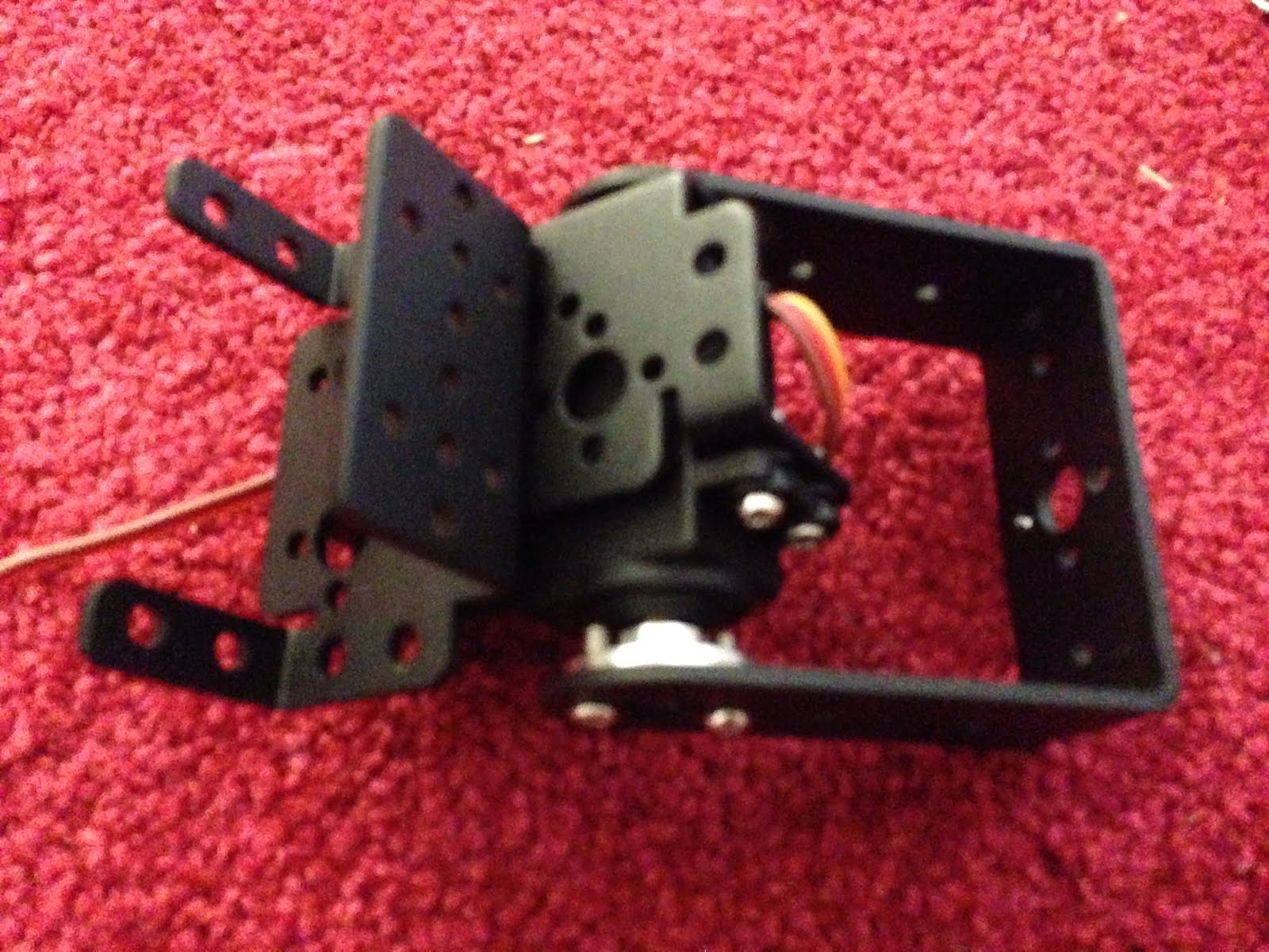


With that bolted on you can insert the servo and horn. You can get a better view from the other side:

Use the servo tester again to make sure that the range of travel is appropriate. Finally you can bolt the servo to the bracket, using the rubber grommets that probably came with your servo to keep everything nice and snug.


Here I've put the wrist servo and gripper into place to get an idea for what it will look like and check the range of movement again, but as the gripper and two servos are quite heavy, we'll leave final assembly till the end.

At this stage I turned my attention of the other end of the build - the base:


The base its quite easy to get started with. There are two larger "flat' u shapes that bolt together to make a platform. Then we bolt a servo bracket to this. A servo goes into the bracket, and then we add attach a second bracket to the servo horn so that we can spin this around.


This is a pretty horrid design. The only documentation I managed to find for one of these arms was a you-tube video, which used a base rotation mechanism like the other three joints, but oriented horizontally. One of the U-bars and a fourth bearing carry most of the lateral forces in that design, but here all the twisting load is on the axle of the servo. I suspect this servo isn't going to live too long. The older design also had a larger/heavier platform so was more stable. This one will need to be bolted to the floor. If possible see you can find a kit which uses the older design. [update: I added an extra set of brackets to support the base better]


Anyway... Working with what we've got, we use the top servo bracket as the basis for another joint, just like the one we built before. In the above pic the bearing is holding the next pair of u-bars in place (they're already bolted into an H). All we need to do next is insert the servo, and we've got a working base:


Now we just need to make the final join that connects the top to the base.
In this picture you can see the H we've just made, and a servo bracket attached to the top left arm (with a bearing again). The one piece left is an L shape which is attached to the back of the servo bracket and the botton of the other U-bar.

Here's a close up of the final joint, and the whole arm from the side, which gives a good idea of how everything goes together. All that's left is to bolt the wrist servo into its bracket and you've got a robot arm!!!


Use the servo tester to run all the parts through their range of motion. Hopefully you checked each joint as you built it to make sure that the servo was correctly centred. If it not quite right then you can try and make some adjustments now, but its tricky.

You'll find that un-powered the arm isn't strong enough to support its own weight, and it will keep collapsing. However powering up each joint will show that in fact its going to be pretty powerful. I guess you could use 6 servo testers(!!) to control the thing, but tomorrow I'll hook this thing up to an Arduino and we can start driving it properly!

Saturday, 19 December 2015

PCA9685 - lots of Servos and LED's with not many wires

We have a fairly predictable cycle of R&D here at Sniff Labs: It starts with us browsing Twitter, AliExpress and Ebay until we spot something cool. Then we get one, write a Sniff Device for it (if necessary), and code up up some demos. We do that for about a month, then push out a "Release". Once a release goes out, we do a blog post for each of the new features, explaining what it does and hopefully inspiring you to take it further...


In the release notes for the last release you'll not that we added support for "pca9685" boards... Then forgot to do the blog post so you've probably no idea what a PCA9685 board is! Well its a chip/board for controlling servos. Now you might say "what's the big deal?". Sniff can already drive servo's pretty easily:


make pulseTime number
when runServo
.forever
..set pulseTime to (1+x)*1000
..set servo to on
..wait pulseTime microsecs
..set servo to off
..wait 20 millisecs


This little snippet of code will drive a servo on a digital output pretty well. Just set "x" to be from 0 to 1 and the servo moves.

That's great if you're running one or two servos from an Arduino, but if you're running lots then the timing will probably start to drift, and you'll use a lot of CPU driving outputs when you could be doing more useful work. If you're on a Pi, then the timings will be a mess to start with, and you might want to be cautious of driving 5V servos from a 3.3v Pi. You should also be worried about output currents from the Pi. Finally you're using up output pins that you might need for something else.

The PCA9685  takes care of all of this: it uses i2c (only two wires), and drive 16 outputs with accurate timings. Breakout boards can typically drive an output output with a moderate amount of power, and you can run the outputs at a higher voltage than the control pins.

Connect up power, data and clock on the left and edge, then plug some leds or servos into the channels across the botton. The VCC pin on the left edge should be connected to the power supply that your controller uses (3.3v or 5v typically) while you provide power to drive the outputs with up to 6V from either the V+ pin or the screw terminals. If that's not enough you can connect the outputs on the right of the board to the inputs of the next board, and drive up to 64 boards with 16 servos on each!!! That's 1024 servos...


make i2c device
make pca9685 device
make pwmChannel number
make pwmValue number


Make a device, and we're ready to go. Lets start with some LED's:

#Channels 0-7 (that's how they're labeled on the board!)
#flash LED's
#Brightness goes from 0-1
when start
.make count number
.forever
..repeat 8 using  count
...set pwmChannel to count-1
...set pwmValue to (sin of (timer*100+count*10)) *0.5+0.5
...tell pca9685 to "set brightness"


Here the LED's are plugged into the first 8 channels of the board, which are numbered 0-7. Just set the channel, and a value between 0 and 1, then tell the pca968 to send that to the hardware. Here Ive set up a sine wave with an offset so we get a nice ripple effect.


#Channels 8-15 (that's how they're labeled on the board!)
#Move Servos
#Position goes from -1 to 1
#This corresponds to the "safe" 1-2mS pulse
#Your Servo may need or like a larger range
when start
.make count number
.forever
..repeat 8 using  count
...set pwmChannel to count+8-1
...set pwmValue to (sin of (timer*100+count*10))
...tell pca9685 to "set servo position"


Doing this with Servo's is just as easy. However the value goes from -1 to +1 and we use the command "set servo position". That's because servo's have some pretty specific timing requirements, so "set servo position" handles all that for you. Depending on your servos you might find that -1 to +1 doesn't give the full range of movement, in which case try increasing the range gradually. A lot of servos need a slightly larger range, but too wide a range of values can damage the servo. The -1 to +1 range is configured to be safe for most hardware, and follows the "standard" behaviour, but try experimenting.


Friday, 18 December 2015

Sniff and Flotilla

I recently posted that my Flotilla Medium starter kit had arrived, and I documented the low level code that you might find useful if you were going to write your own code to talk directly to the hardware. You could actually to that yourself entirely in Sniff using the serialPort device, but the plan was always to add Sniff devices to support the Flotilla.

I've now got those working, and you can download them and add them to an existing Sniff installation. Normally I'd release this as part of a full Sniff release, but it's getting close to Xmas, and I probably won't get a full release out until the new year. There's a particular cool feature that needs a little more work, so I'm holding off until that's fully working. In the mean time here are the files you need to try it out. The drivers (in the XHosted folder) need to be added to the lib/XHosted folder you already have. There are also some examples which I'll talk about now... [Update: as of R24 Flotilla support is included i the current release]

To compile the examples, use the normal "sniff" commands. On Unix platforms the Flotilla gets found the same way as an Arduino when you run "./setup". On Windows you'll need to explicitly tell it by typing:

export ARDUINODEV=COM4

or whatever port you have it on in the shell after you've run setup.


make flotilla device

make light flotillaLight device
make brightness number

when start
.forever
..tell light to "update"
..say join "Brightness:"[brightness]
..wait 1 secs


The first thing you need to do is make a flotilla device. This represents a the flotilla dock and much like the dock you don't actually need to do much with it. It just acts as a hub for all the other devices you might want to use.

Once you've got a dock you can make an actual module and do something with it. Here I've attached a light module, by making a flotillaLight device and calling it light. The Flotilla has 8 ports, but you can plug the module into any of them - Sniff will look for a light sensor and use whichever port it finds it on. However if there isn't one plugged in then it will give and stop your program.

Alternatively you can specify which port the module is plugged in to:
make light flotillaLight device 4

This has the advantage that if you've not plugged it in yet you'll get a warning message but your program will keep running, and you can plug the device into port 4 later. In future you'll also need to use this if you want to plug in multiple devices of the same type (the mega-treasure chest includes two light modules and two motors). At the moment you can only attach one of each type of module, but that'll be fixed before the full release.

To read or write a sensor, just tell it to "update". You can also tell the dock to update, which you might want to do if you're not updating any other sensors for a long time just to give it a chance to do any housekeeping work, but this generally shouldn't be necessary.

In the case of the Light sensor "update" sets the variable brightness and we just print it out.


make flotilla device
make thermometer flotillaWeather device
make temperature number
make pressure number


when start
.forever
..tell thermometer to "update"
..say join "temp :"[temperature]
..say join "pressure:"[pressure]
..say ""
..wait 1 secs


Weather works in the same way, setting temperature and pressure.

make flotilla device
make keypad flotillaTouch device 
make key1 boolean
make key2 boolean
make key3 boolean
make key4 boolean


when start
.forever
..tell keypad to "update"
..if key1
...say "1" 
..if key2
...say "2" 
..if key3
...say "3" 
..if key4
...say "4" 
..wait 0.1 secs

Touch sets the four variables to be true of false depending on if the button is pressed.


Rainbow is the most complex module in the Medium kit, and works just like the neoPixel device, except that we change the names.

make flotilla device
make rainbow flotillaRainbow device
make rainbowShade list of numbers
make rainbowColor list of numbers


rainbowShade is the brightness (between 0 and 100), while rainbowColor is the hue between 0 and 360. 

Rainbow Thermometer

Lets look at how we can use that to make "thermometer":

make flotilla device
make sensor flotillaWeather device 
make temperature number
make pressure number

make rainbow flotillaRainbow device
make rainbowShade list of number
make rainbowColor list of number


make counter number


when start
.repeat 5
..add 0 to rainbowColor
.
.forever
..tell sensor to "update"
..#say [temperature]
..
..delete all of rainbowShade
..set counter to 1
..repeat 5
...if counter*2+20<temperature
....add 10 to rainbowShade
...else
....add 0 to rainbowShade
...change counter by 1
..
..tell rainbow to "update"

We make a rainbow and a weather device, then fill the rainbowColor list with 0's representing red. Then we read the temperature, and fill in rainbowShade. Using counter, we calculate a value for each LED from 22 to 30 degrees. If the actually temperature is greater than that we turn the LED on (red). If its less than that we turn it off.

The result is a thermometer that displays temperatures from 20-30 degrees in 2 degree steps. This is a handy range as its easy to see the display change just by holding the sensor.

Altimeter

One of the neat things you can do with the weather sensor is measure altitude. We did this last summer using an Arduino and BMP180, but now we can do it with Flotilla. The code required virtually no changes - just swapping out the BMP180 for a flotillaWeather module:

make flotilla device
make sensor flotillaWeather device
make pressure number
make temperature number

make altitude number
make seaLevelPressure number
make seaLevelTemperature number

make message string

when start
.tell sensor to "update"
.set seaLevelPressure to pressure
.set seaLevelTemperature to temperature+273.15
.
.forever
..tell sensor to "update"
..broadcast calculateAltitude and wait
..set message to join "Temperature:" [ temperature ]
..say message
..set message to join "Pressure:" [ pressure*0.01 ]
..say message
..set message to join "Delta:" [ (pressure-seaLevelPressure)*0.01 ]
..say message
..set message to join "Altitude:" [ altitude ]
..say message
..say ""
..wait 1 secs


when calculateAltitude
.set altitude to seaLevelPressure/pressure
.set altitude to ln of altitude
.set altitude to altitude * 0.1903
.set altitude to e^ of altitude
.set altitude to seaLevelTemperature * (altitude-1)
.set altitude to altitude/0.0065


Check the original post for more details on this one. You might need a longer USB lead to get the most out of this example but its still pretty cool

Simon

Finally I wanted to do something with Touch, so I build a game of "Simon". The computer flashes the Rainbow LED's in a sequence which gets longer each turn, and you have to copy the patten on the keypad.

make flotilla device

make rainbow flotillaRainbow device
make rainbowShade list of numbers
make rainbowColor list of numbers


make keypad flotillaTouch device 
make key1 boolean
make key2 boolean
make key3 boolean
make key4 boolean

make pattern list of numbers

when start
.repeat 5
..add 0 to rainbowShade
.
.add 0 to rainbowColor
.add 120 to rainbowColor
.add 240 to rainbowColor
.add 60 to rainbowColor
.
.tell rainbow to "update"
.
.forever
..broadcast playGame and wait
..wait 5 secs

This is standard flotilla setup. Then we have a list called "pattern" that we're going to store the pattern so far in. We put four distinct colours in the rainbowColor list, but turn all the LED's off by setting their brightness to 0. Then we're ready to go...


make counter number
make led number

when playPattern
.set counter to 1
.repeat length of pattern
..set led to item counter of pattern
..replace item led of rainbowShade with 10
..tell rainbow to "update"
..wait 0.3 secs
..replace item led of rainbowShade with 0
..tell rainbow to "update"
..wait 0.1 secs
..change counter by 1


To play the pattern we  simply loop over the list turning on the required LED of a short period with a smaller time gap between each.

when playGame
.delete all of pattern
.forever
..add pick random 1 to 4 to pattern
..broadcast playPattern and wait
..
..set counter to 1
..repeat length of pattern
...set led to 0
...repeat until not led = 0
....if key1
.....set led to 1
.....wait until not key1
....if key2
.....set led to 2
.....wait until not key2
....if key3
.....set led to 3
.....wait until not key3
....if key4
.....set led to 4
.....wait until not key4
...if not led = item counter of pattern
....broadcast flash and wait
....stop script
...change counter by 1


To actually play the game we add a random led to the pattern so far then play it back. Now we need to check the the touch pad. We go through the pattern one step at a time and wait for a key to be pressed. We record the key press then wait for the key to be released.... This is important otherwise just touching one key would be recorded multiple times.

Then we check that the key pressed was the right one. If it wasn't we run a script called flash to indicate failure, and end the came. If we get to the end of the pattern then we go background, add another light to the sequence and keep going!


when start
.forever
..tell keypad to "update"
..set dummy to pick random 1 to 10
..wait 0.01 secs

You'll not that when I'm checking the buttons I'm not calling update. I need to keep calling it, otherwise the variables representing the keys will never change, but it would make the code messy, so instead I've got a separate script which just keeps calling update. (it also randomises the game by throwing away random numbers - I've talked enough about that in other posts).


when flash
.repeat 5
..delete all of rainbowShade
..repeat 5
...add 10 to rainbowShade
..tell rainbow to "update"
..delete all of rainbowShade
..repeat 5
...add 0 to rainbowShade
..tell rainbow to "update"

That just leaves flash which is pretty obvious.

Conclusions

And that's about it. So far I'm pretty impressed with the hardware. It's really nicely built, and the design allows for lots of expansion. Price wise its not cheap - the Medium kit with a dock and four modules is £39, but its not too bad. Based on the prices of the different sized starter kits I'd expect individual modules to cost between £5 and £10 (some costing more than others) when they become available. Many of the modules have arduino compatible equivalents that cost about £1, but that's from overseas suppliers. From a regular UK seller they'd cost about £4 so a couple of pounds extra to have something kid friendly and just plugs in and works is actually good value. For comparison LittleBits charge $18 for their temperature sensor!!! On the downside, having got the Medium kit up and running,  I want to do more with it than I can with just four modules, so I will need to get more modules...

Where the HW has real potential is for expansion. The design allows new modules to be added. There are currently 12 available, but I'm surprised the so called "pirates" at Pimoroni forgot to include a compass. A 16x2 LCD text screen would also be simple to add. Right now its a nice piece of fun, but wth an ever expanding range of modules at good prices, then this could be a really great piece of kit.

Tuesday, 15 December 2015

Hacking the Pimoroni Flotillla

It's finally here! Way back at the beginning of the year Pimoroni announced a project on kickstarter to make it childproof to plug sensors into a Raspberry Pi. While we love Arduino, the Flotilla gave the chance to do similar kinds of physical computing with a much younger age group. While Sniff is possibly a bit advanced for the Flotilla's core audience, children grow up... and taking cool hardware that was bought for one age group and letting them reuse it with Sniff when they're a bit older not only makes the equipment costs more manageable, but also lets kids focus on what they're doing in software without getting scared of new hardware.

Plus they looked pretty cool, and the engineer behind them - Phil Howard promised they'd be good and hackable, so lets go...


Finally (a little late, but just in time for Christmas!) it arrived. Now the normal thing to do (and what I would normally do with new hardware) is follow the instructions to check its all working right, before pulling it apart to see how it works. However in this case I decided to jump right in, and see what makes it tick straight away. One of the reasons for that is that Flotilla is designed to work with Raspberry Pi. I understand Pimoroni's justification for that (marketing and support issues), but Flotilla is totally wasted on Pi. It's USB so plugs into a regular computer and works just fine, and the idea of having a simple USB breakout for hardware boards is that you don't need stuff like GPIO, so you're much better off sticking with your regular computer.


So I plugged it straight into my Mac to see what happens...

First thing is we get a serial port,so lets fire up a serial monitor and see what happens. You need to set your serial port to 9600baud, and send <CR> carriage returns - NOT LF/Linefeeds, or CR/LF. Then you're in business.

v<CR>

V for version. Typing this tells you all about your dock
# Flotilla ready to set sail..
# Version: 0.1
# Serial: 0c0008003458363737330f
# User: ian
# Dock: myDock

As you can see you can put your name in, and if you've  got more than one dock you can give each one a different name. You can change these who the "name dock" and "name user" commands:

n u Ian
n d myFlotilla

Now for the fun bits! Plugging in a device to one of the eight ports, and the Dock sends you a message:

c 4/rainbow

c for connect, the port number, and then the name of the device connected. And when you disconnect it you get a disconnect message:

d 4/rainbow

If you don't fancy keeping track of all that, you can just type "e" to enumerate to get a list of all connected devices:
c 2/weather
c 4/rainbow

You can get this in a slightly more human friendly, but less computer friendly debug message by typic "d".

# Debug information:
#    Resources:
#       SRAM free: 1362 bytes
#    Load:
#       Main loop duration: 93ms (0us)
#       Main loop cycles per second (fps): 10
#    Channels:
#       0 - vacant
#       1 - vacant
#       2 - weather (0x77)
#       3 - vacant
#       4 - rainbow (0x54)
#       5 - vacant
#       6 - vacant
#       7 - vacant

One minor quirk is that the channel numbers are numbered 0-7 in the opposite direction to the numbers on the board which go from 1-8. That means that "weather" on channel 2, is actually plugged into the socket numbered 6 (8-2=6). Probably best handle that in the low level software somewhere.

Once a device is plugged in, then if its an input device like the weather it starts sending status updates:
u 2/weather 2182,101032
u 2/weather 2181,101032
u 2/weather 2182,101034

Here the temperature is 21.8 degrees and the air pressure is 1010.

Touch sends a message whenever one of the buttons changes state:

u 3/touch 0,0,0,0
u 3/touch 0,1,0,0
u 3/touch 0,0,0,0

Light sends three values, but looking at the Python code, the first value is the brightness.

Most of the input devices should be pretty obvious.

Rainbow is the only output device I have (I got the medium kit ), and they're a but more tricky.

The command to talk to  a device is "s" so to turn on some of the LEDs we type:

s 4 0,0,255 , 255,0,0 , 0,255,0 , 0,255,0 , 255,255,255

The Rainbow is on channel/port 4, and we need to send it 5 rgb triples. 255 is full brightness. 0 is off. 

Anyway - that's all the info I need to get this thing running in Sniff...

[Update:theres now a follow up to this post, which explains how to easily use  Flotilla in Sniff along with a bunch of example projects]

Monday, 7 December 2015

Sniff on MBED (on the STM411 Nucleo)

We added MBED support to Sniff a while back, but didn't really announce it, as there were a few things about the install and setup process that are a bit tricky. At the time MBED 2 provided an easy to use on-line system, which wasn't really powerful enough to support Sniff, and some a fairly half hearted support for exporting to off line toolchains - many of which were commercial. We hoped that situation would change, and now with the introduction of MBED 3 that's all been replaced with a random collection of python scripts, with multiple package dependancies, that don't support most of the hardware, and fail to compile the demo examples... I don't know what's going on with the project, but find it strange that while the MBED2 system focused so much on being a simple online tool, then MBED3 is a sprawling complex off line tool.

In any case it doesn't look like MBED2 is going to change any time soon, so its probably best to just tell you what support we do have, and you can figure out if its useful for yourself...  [Update: It got easier!]

When we were looking to port to MBED we needed to pick a board to work with, and most of them were simply overpriced, and underpowered. Cheap, direct from china sources of Arduino and other boards have pushed prices down to the point that spending £40 to £60 on a board with an M0 or at best an M3 ARM processor doesn't make a lot of sense. By comparison an M3 Arduino Due clone is under £10.

Then we discovered the STM Nucleo series. STM want serious developers to use their chips in commercial products, and one of the ways they do that is by putting them in dev boards so they can play with them. They have a whole series of boards with different versions of their processors on, each with slightly different performance characteristics. However we're not interested in the fine details - we want a fast chip with lots of memory, and we want to pay as little as possible for it...

In that case meet the STM32F411 Nucleo! It's an M4 series ARM at 100MHz, with 512K flash and 128KRam. With those specs its matching or exceeding the Due in every respect. (M3,84MHz,512,96). It even includes Arduino Uno comparable headers, and does a better job of putting things like SPI in the right place than the Due does. It's even semi-5V tolerant, though there a few gotcha's so probably best to treat it as 3.3v only, and be happy it doesn't blow up when you make a mistake.

But its got one crazy trick up that means its going to run Sniff better than anything else... IT'S GOT AN  FPU!!!!! Variables in Sniff are floating point, which is a big problem if you're worried about performance on an embedded chip because they're slower to calculate with and the CPU's we use for that sort of thing don't have FPU's to help... except the N411 (I'm going to call it that because STM didn't give it a fun catchy name) does.

Having explained how this board just might be the best thing out there, you're probably asking "ok - how much?". We'll I saved the best TWO details for last. It's costs under £10... from official major UK suppliers like CPC, Farnell, Mouser etc. That is an insane price. For some eBay/Ali clone it would be still great, but this is for an official, supported first party board, through official distribution channels, it even comes in packaging with art work and stuff! An official Due is about £30.

If I've convinced you to rush of and order one, then great... ... .... welcome back, but lets build some code.

Installation

As I noted earlier the MBED site is a bit of a mixed message right now, but the first thing to do is go to the MBED 2 dev site, and get your board working there. Create a project for your new board, and compile it. You should end up with an executable you can drag to the usb drive that appears when you plug in your board. With that working, right click on the project and "export" it for toolchain "GCC Arm Embedded". Not only does this check everything is working, but (as far as I know) it's the only easy way to get hold of the libraries for your board... we'll need those later.

Now we need to install the C compiler (if you haven't already got it). You can do that by following the MBED instructions here: http://yottadocs.mbed.com/#installing.  Ignore the bits about Yotta - just install arm-none-eabi-gcc and we're almost ready to go.

Go back to the demo project you downloaded from MBED and you should now be able to compile it (in a terminal window) simply by typing "make" (if not, check your gcc is installed properly). Inside that folder you should have a folder called "mbed" which contains the mbed libraries for your board. Now you need to tell Sniff where they are by editing the first line of  SNIFFDIR/bin/n411-sniff so that it has the name of that mbed library folder (not the project folder).

[Update: Install the Yotta App/Installer for Mac or Windows and you're good to go! On Linux just install the compiler and the rest should work!]

Finally we're ready to compile a Sniff program, by simply typing

n411-sniff hello.sniff

Performance

To test the performance I modified the prime numbers example:
make num number
make test number

make found number

when start
.set num to 2
.repeat until num > 1000
..set test to  2
..repeat until num mod test = 0
...change test by 1
..if test = num
...change found by 1
..change num by 1
.say [timer]
.say [found]

The changes are that we now test to 1000 (so it takes longer), and rather than printing out the results (which would only test the serial I/O speed! ), it counts them, then prints out how long it took. No this isn't a fast way to find primes - the point is to stress the processor.

For a couple of baselines this took about 0.002s on my (old) Mac desktop, while the good old Arduino Uno took 2.129s (this is consistent as unlike the Mac its not doing a bunch of other things at the same time). Initial conclusions: the Uno is slow, but we know that. The AVR is an amazing chip, but its 16MHz, 8 bit and no FPU. Fast maths is not what its designed to do.


That Arduino Due clocks in at, in some respects, a more disappointing 0.857s. It's over twice as fast, but then again - it's a 32bit chip running at over 5 times the clock rate.


Our N411 takes 0.346s. That's almost 10 times faster than an Uno, and 2.5 times faster than a Due despite similar clock rates. Also the N411 code was 16468bytes while the Due used 30092. While they both have 512K of flash, the n411 (at least for this very simple test) is using it more efficiently - which you'd expect from the improved CPU architecture.


In Use

Working on the initial development on OSX Yosemite the board ran smoothly. There was an annoying "drive disconnected" message every time the N411 reset itself, but it was rock solid. One really nice feature is that MBED doesn't use the serial connection for programming which means that you can leave a serial monitor open, rather than having to disconnect each time. El Capitan has been a little more glitchy, but that might just be my setup.

The Arduino pinout is a big help transitioning, but remember its 3.3V. Shield should work, but not all will, and documentation on shields is usually bad. In addition to the Arduino headers there are also "morpho" headers which is STM's own header layout, which have all of the "arduino" pins plus more. In Sniff if you use the D1-13 or A0-5 pin notation then that referers to the Arduino pins, while bare numbers 1-64 refer to the morpho layout.

Overall most of the embedded examples ran well on the N411, and while in theory the Due is an Arduino, the extra features and support that brings typically are restricted to the AVR chipset. The N411 is an amazing board, and being able to just order one from a UK supplier for a sensible price should make us all really excited.

So why aren't we screaming about it? toolchain. Sniff uses the Arduino toolchain to target Arduino which handles all of the board issues. You download the Arduino app and you're good to go. Installing the compiler and then downloading the libraries for each specific MBED board is just messy. We've got a basic framework for supporting multiple MBED boards but supporting each board is a separate piece of work.

For most MBED boards that's just not worth the effort. They don't offer a compelling price/performance mix to make them worth moving from Arduino, but the N411 is a bit special and deserves some special attention.